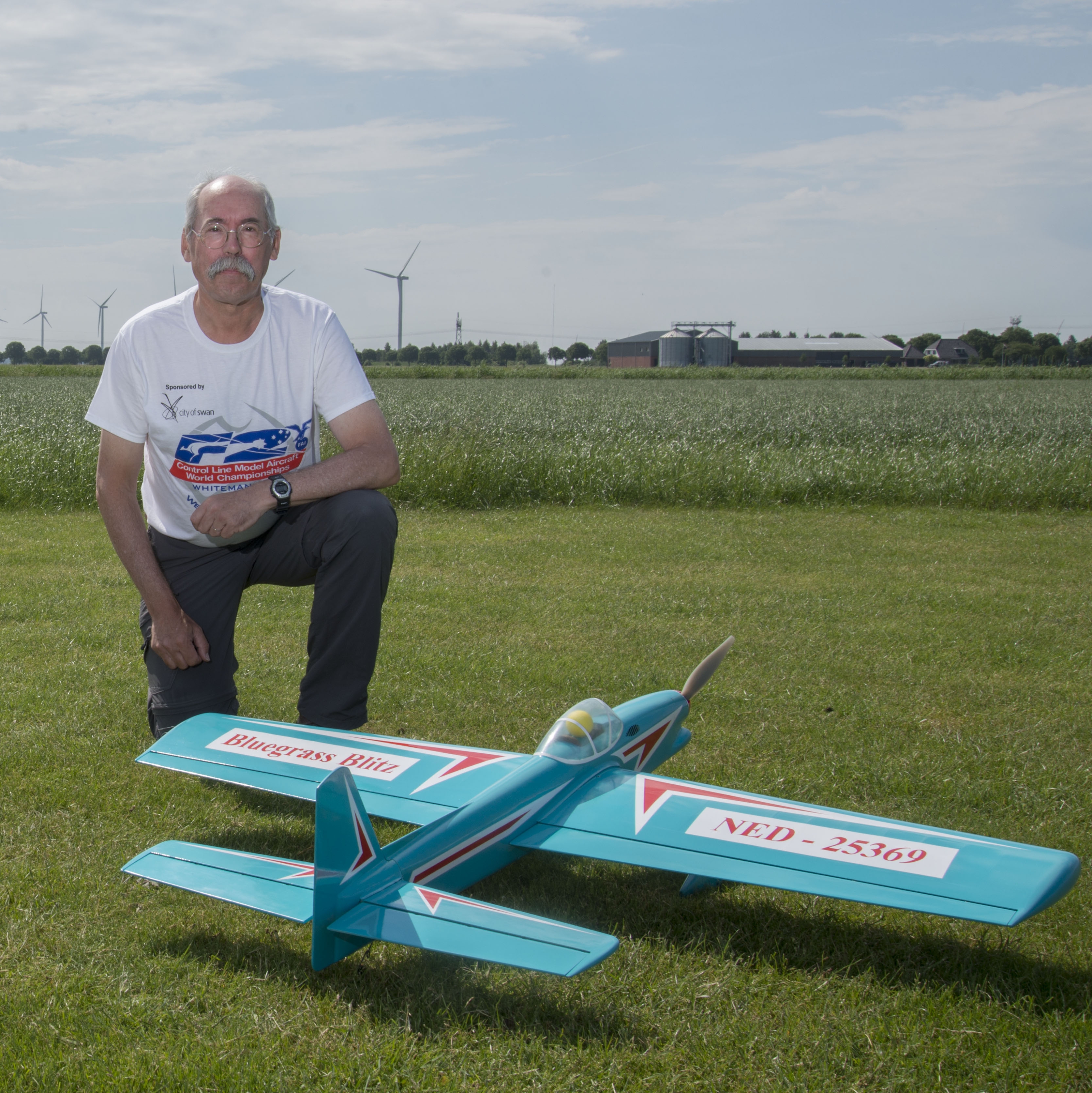
As a continuation of my nostalgic kick at the moment I'm building my first control liner for fifty years and chose the Aeromodeller free plan from April 1973, the Jay-Pee, a profile stunt trainer said to be for a 2.5cc diesel. I built one of these in the day and it ended up a nylon bag of bits, after very little flying, but it was a relatively simple build from the plan and I've now got a wing together for my 2023 build and will be making a start on the fuselage shortly.
However I'm in a quandry regarding how to arrange the leadouts. The plan has piano wire leadouts from the paxolin bellcrank to about three bays out from the centre and then states that these are bound and soldered to heavyweight laystrayte cables, which pass through brass tubes inserted into the wingtip. I seem to recall that on mine I just used 22swg pianowire, with an L bend and soldered cup washer on the bellcrank end fed through the wingtip and then fashioned a little number 4 shaped bend in the wire outside the wingtip, to which the loop on the control lines were attached. I can find no mention of these bent wire ends on the tinternet to refresh my memory, but have seen lots of talk that you shouldn;t have piano wire leadouts outside the tips, because they are easily bent and damaged. There's stacks of information online on AMA rules, pull tests, the merits of crimping, soldering, epoxy, heatshrink in making up lead outs, but I'm missing a very basis point here.
There's my question - I have some brand new Sullivan 50ft lines and a brand new Sullivan handle, which have both been in my modelling bits for well over 20 years. These both have wee brass eyelets bound and crimped on the ends of the wires and I can't see any way in which to attach these either to the model or to the handle/ Is is necessary to create some form of swivel for both ends of the lines? This is such a basic question that my trawling through internet sites discussing control liners seem to omit this information.
Control line leadouts and terminations
-
leccyflyer
- Posts: 115
- Joined: 30 May 2023, 16:52
- Location: Perthshire
- Contact:
-
Phil_G

- Posts: 608
- Joined: 15 Feb 2018, 23:32
- Contact:
Re: Control line leadouts and terminations
I'd try Barton MFC Brian: (they're PANDAS friendly!)
https://controlline.org.uk/phpBB2/index.php
Barton is the UK control line club, they will know!
https://controlline.org.uk/phpBB2/index.php
Barton is the UK control line club, they will know!
-
leccyflyer
- Posts: 115
- Joined: 30 May 2023, 16:52
- Location: Perthshire
- Contact:
Re: Control line leadouts and terminations
Thanks Phil - I've been a member at the Barton MFC control line forum for a wee while, as a lurker, but couldn't see an answer to my query, so I've just reposted that there and will see how we get on.
-
F2B
- Posts: 200
- Joined: 16 Feb 2018, 11:23
- Location: 20 m NE of Amsterdam
Re: Control line leadouts and terminations
The idea of using solids on the bellcrank side and flex on the lead out side is OK in itself, though an L-bend with a soldered washer is asking for trouble.
Making it a Z-bend or even better, a cornered U bend will make things safe.
You mentioned an AWG system that has no meaning at all to me. I'd take 1 mm pianowire... For the flexible part I'm using cycle breaking cable, also 1 mm - galvanised, not SS as that solders not very good (not at all
  ).
).
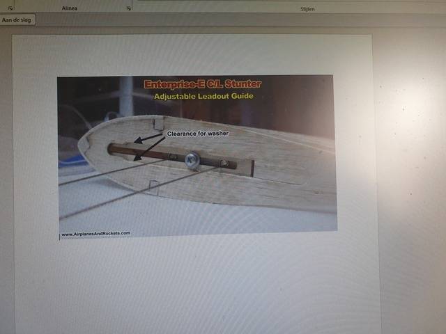
Two improvements I've been using since the mid-1980-ies are adjustable lead out guides and a tipweight box ( instead of fixed glued in weight),
making set up and trimming the model a breeze instead of a never ending struggle to getting things right.
Here are some examples of adjustable leadouts:
For a flat wing tip this would work, a small slider block with two brass tubes and a locking bolt.
For built up tips I'd do it this way (I always make two sliders, one per line):

For hollowed out tip blocks I did it this way:
The model:
Here's how to make eyelets on cables: https://www.modelbouwforum.nl/threads/o ... te.284626/
It's in Dutch, so don't hesitate asking here when not clear.
THE thing to watch out for is making the transition between the flexible cable and the solid eyelet as smooth as possible.
Otherwise you'll be setting things up for metal fatigue.
These are the type of connectors I'm using between lines and leadouts or handle:
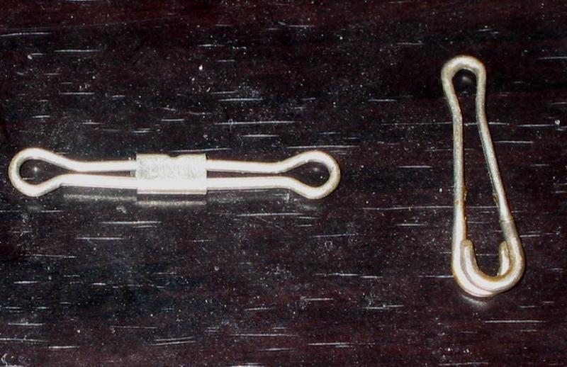
NEVER EVER use something like this ( I've lost a model because of the ball link failing):

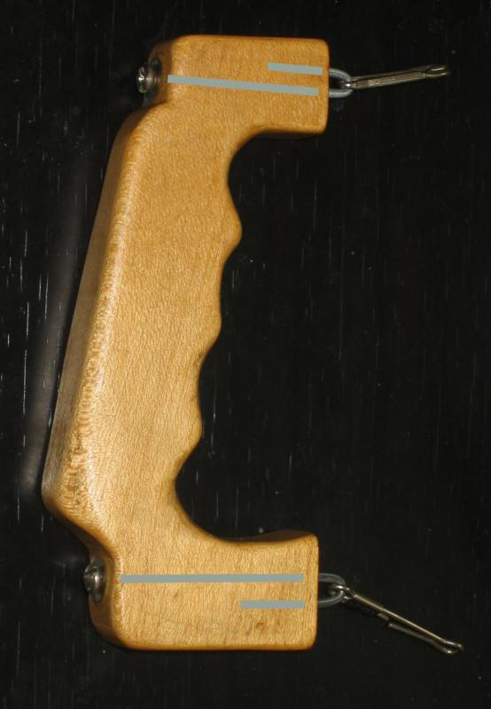
Oh yes, did I mention that an adjustable handle will save you many head aches?
A block of Maple, two 2 mm spokes and 2 washers....:
Making it a Z-bend or even better, a cornered U bend will make things safe.
You mentioned an AWG system that has no meaning at all to me. I'd take 1 mm pianowire...
Two improvements I've been using since the mid-1980-ies are adjustable lead out guides and a tipweight box ( instead of fixed glued in weight),
making set up and trimming the model a breeze instead of a never ending struggle to getting things right.
Here are some examples of adjustable leadouts:
For a flat wing tip this would work, a small slider block with two brass tubes and a locking bolt.
For built up tips I'd do it this way (I always make two sliders, one per line):
For hollowed out tip blocks I did it this way:
The model:
Here's how to make eyelets on cables: https://www.modelbouwforum.nl/threads/o ... te.284626/
It's in Dutch, so don't hesitate asking here when not clear.
THE thing to watch out for is making the transition between the flexible cable and the solid eyelet as smooth as possible.
Otherwise you'll be setting things up for metal fatigue.
These are the type of connectors I'm using between lines and leadouts or handle:
NEVER EVER use something like this ( I've lost a model because of the ball link failing):
Oh yes, did I mention that an adjustable handle will save you many head aches?
A block of Maple, two 2 mm spokes and 2 washers....:
F2B or not to be....
-
leccyflyer
- Posts: 115
- Joined: 30 May 2023, 16:52
- Location: Perthshire
- Contact:
Re: Control line leadouts and terminations
That's great information F2B - thanks so much. I originally made up the bellcrank with Z bends on the piano wire, but having researched further, decided that might not be the best method. I'm much happier now that I've read that.
-
Spike S
- Posts: 183
- Joined: 16 Feb 2018, 14:59
- Location: Salisbury UK
Re: Control line leadouts and terminations
Ancient 'hack' for making easy Z-Bends without fine-nose pliers:
Some inferior grades of Piano wire may fracture during the last stage, but you didn't want to use that stuff anyway. Better to find out before than in flight !
Some inferior grades of Piano wire may fracture during the last stage, but you didn't want to use that stuff anyway. Better to find out before than in flight !
Spike S
(Tune for maximum smoke)
(Tune for maximum smoke)
-
F2B
- Posts: 200
- Joined: 16 Feb 2018, 11:23
- Location: 20 m NE of Amsterdam
Re: Control line leadouts and terminations
To be more complete, I'd like to explain that I'm never using solid connections on the bellcrank side myself.
I explained using solids as this is how it's sometimes done nowadays, but not my favorite contraption.
With my all flexibles, the bellcrank receives brass bushings that are, more or less, rounded off as to not 'saw' throug the cables
Then my (~1 mm) galvanised steel lead out cables are lead through in a flattened loop that can be bound with copper wire and soldered.
Or, as I do, 1/2 " of brass tubing, pinched flat on both ends, but with a 90 deg difference. Then solder, no cable should be overheated, use an electric iron and lead/tin solder, resin core.
When setting up the controls, make sure the bellcrank's longitudinal axis (from leadout hole to leadout hole) is parallel to the fuselage axis.
Then connect the control rod to the elevator that must be perfectly in line with the stab.
This provides you with controls that are symmetrical, both up and down.
Overlooking this simple set up rule often results in a model that is hard to fly, making people believe (even simple) aerobatics must contain at least some magic ingredient. In fact it does: a light, true built model with ( super light moving) symmetrical controls.
Therefore an elevator pushod can't be stiff enough. Pianowire is a no-go, carbon tube with proper fittings works wonders.
If you are able to mount the tank in such a way that you can move it up and down a few millimeters.
This way you can set up the tank/engine combination so you're having exactly the same behaviour in loops and bunts.
Again, making flying the aircraft where you want it, much easier.
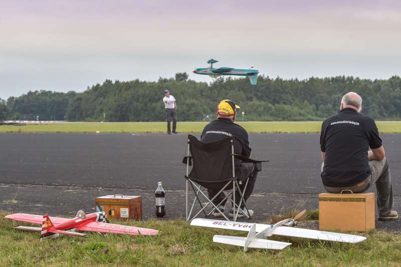
Why am I telling this, while the subject is 'just' a 2,5 cc , diesel powered model?
Because we found that applying what we'd learned from full size F2B aerobatics on smaller aircraft, actually made them better.
Good luck, lots of fun and don't hesitate to ask!
If a reaction seems overdue, just send me a personal message.
Bruno
I explained using solids as this is how it's sometimes done nowadays, but not my favorite contraption.
With my all flexibles, the bellcrank receives brass bushings that are, more or less, rounded off as to not 'saw' throug the cables
Then my (~1 mm) galvanised steel lead out cables are lead through in a flattened loop that can be bound with copper wire and soldered.
Or, as I do, 1/2 " of brass tubing, pinched flat on both ends, but with a 90 deg difference. Then solder, no cable should be overheated, use an electric iron and lead/tin solder, resin core.
When setting up the controls, make sure the bellcrank's longitudinal axis (from leadout hole to leadout hole) is parallel to the fuselage axis.
Then connect the control rod to the elevator that must be perfectly in line with the stab.
This provides you with controls that are symmetrical, both up and down.
Overlooking this simple set up rule often results in a model that is hard to fly, making people believe (even simple) aerobatics must contain at least some magic ingredient. In fact it does: a light, true built model with ( super light moving) symmetrical controls.
Therefore an elevator pushod can't be stiff enough. Pianowire is a no-go, carbon tube with proper fittings works wonders.
If you are able to mount the tank in such a way that you can move it up and down a few millimeters.
This way you can set up the tank/engine combination so you're having exactly the same behaviour in loops and bunts.
Again, making flying the aircraft where you want it, much easier.
Why am I telling this, while the subject is 'just' a 2,5 cc , diesel powered model?
Because we found that applying what we'd learned from full size F2B aerobatics on smaller aircraft, actually made them better.
Good luck, lots of fun and don't hesitate to ask!
If a reaction seems overdue, just send me a personal message.
Bruno
F2B or not to be....
-
MJF
- Posts: 81
- Joined: 12 Jun 2018, 15:22
- Location: Ontario Canada
Re: Control line leadouts and terminations
There are many ways of doing this, here is mine that I find works well.
Attached are a couple of photos of a 3" bellcrank (probably should have made it 4" for my model) I made up using 2 layers of 1/16" fiberglass sheet epoxied together, some brass tubing and Sullivan "C-D" lead out cable for a 40 (6.5cc) size cl model.
I wire wrapped the ends and coated them with some slow drying epoxy then put on heat shrink tubing on the ends near the bellcrank.
In the past I have also used small lengths of brass tubing and crimped them to secure the end loops.
Also used a small RC bearing in the bellcrank from an RC car sized to fit the pivot bolt.
- wire wrapped but not yet coated with epoxy
- installed in the wing. Note split pin thru nut & bolt. It is not going anywhere. Could have also used JB weld to secure the nut to the bolt.
-
F2B
- Posts: 200
- Joined: 16 Feb 2018, 11:23
- Location: 20 m NE of Amsterdam
Re: Control line leadouts and terminations
The only lines I ever broke were stainless steel, finished as per AMA rules.
I never broke anything Laystrate/Staystrate in over 50 years.
Go figure...
When soldering, never ever use anything but rosin core flux and always provide a gradual hard/soft transition to any termination.
As for lead outs, don't resort to anything flimsy as under 1 mm steel cable.
The latter was always involved in all failuresqq I've seen...
F2B or not to be....