Yes, it programs the fuses perfectly. All is good again. Time for a beer.
Thanks again,
Wayne
DigiSpark with 6 input/output pins, homebrew fuse-programmer
-
waynew17
- Posts: 25
- Joined: 14 Feb 2022, 17:24
-
RaymondvM
- Posts: 6
- Joined: 16 Nov 2023, 10:15
Re: DigiSpark with 6 input/output pins, homebrew fuse-programmer
Hello to all the genius hard and software experts,
I build the fuse programmer, and it works wonderwell!
Now, i encounter the following: when trying to flip a debuffed (linear Digispark) it does noet work
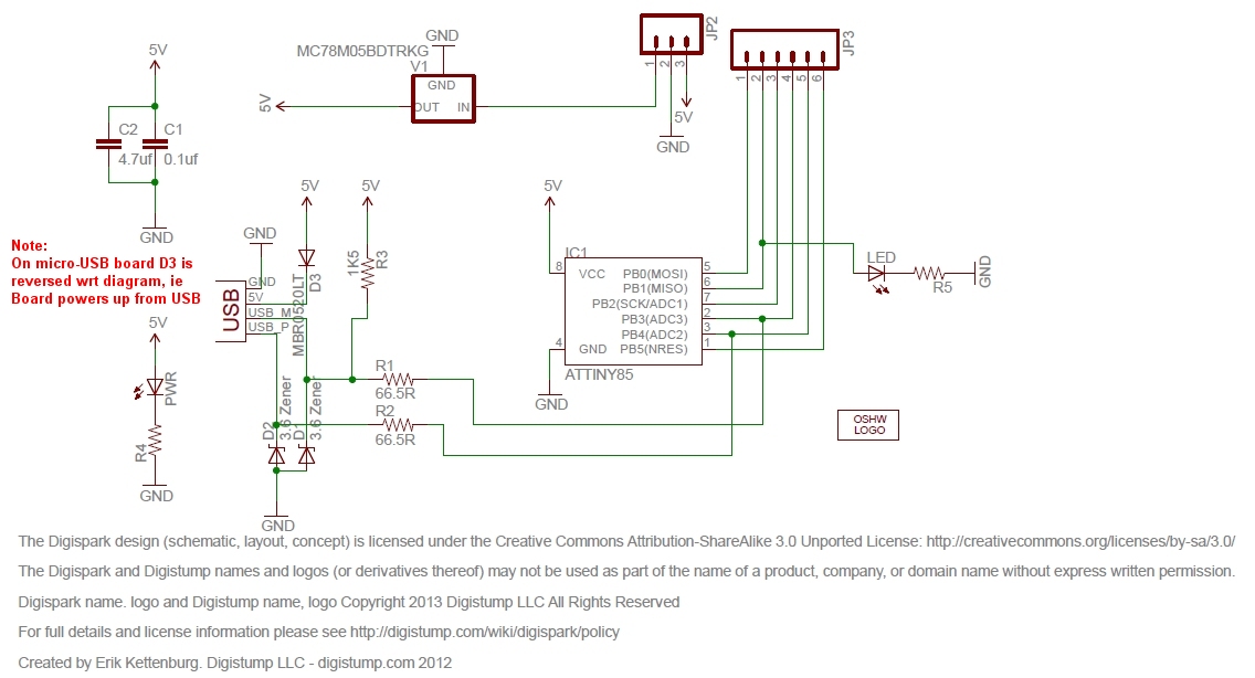
In my debugging, I found out that removing D2 caused the issue. All other components can be removed, but when D2 is removed, only strange fuse values appear.
What I note: with D2 in place the Vcc led lights up rocksolid during read and write. With D2 removed, the Vcc led faints a little during the 3 read-write actions.
I was as last resort thinking to add a D2 3.3 V zener and 68 ohm resistor via a header on the programmer, so I can place it when flipping a debuffed Digispark.
Any-one any idea on what could be going on?
I would appreciate some feedback!
Regards,
Raymond.
I build the fuse programmer, and it works wonderwell!
Now, i encounter the following: when trying to flip a debuffed (linear Digispark) it does noet work
In my debugging, I found out that removing D2 caused the issue. All other components can be removed, but when D2 is removed, only strange fuse values appear.
What I note: with D2 in place the Vcc led lights up rocksolid during read and write. With D2 removed, the Vcc led faints a little during the 3 read-write actions.
I was as last resort thinking to add a D2 3.3 V zener and 68 ohm resistor via a header on the programmer, so I can place it when flipping a debuffed Digispark.
Any-one any idea on what could be going on?
I would appreciate some feedback!
Regards,
Raymond.
-
Phil_G

- Posts: 608
- Joined: 15 Feb 2018, 23:32
- Contact:
Re: DigiSpark with 6 input/output pins, homebrew fuse-programmer
Hi Ray
There have been several PCB layouts for the Digispark, to the same schematic but arranged differently.
I wonder if your Digispark has PB4 routed differently? Are all your DigiSparks identical?
With a multimeter you could test from the P4 header to pin 3 of the ATTiny85, it should be a direct connection.
I cant see how the absence of D2 could influence things otherwise...
From the description I would suspect a power feed problem, probably in the ground, such that ground is actually
feeding through D2 into the Attiny85 port. Maybe.
Did you cut off the USB plug, if so no hairline shorts or copper shards?
A strange problem, not one I've seen before (in dozens of defluffed Digisparks), anyone else seen this oddity?
Cheers
Phil
-
RaymondvM
- Posts: 6
- Joined: 16 Nov 2023, 10:15
Re: DigiSpark with 6 input/output pins, homebrew fuse-programmer
Thanks Phil, you are fast as lightning!
Now that I know ut should work with the defluffed ones, I will try to figure it out.
It happens to both cut as full ones.
Grounding sounds as a possible cause. Especially as the Vcc light is not rock solid.
All boards are identical, recently ordered in far east, showing rev.3. Most probably clones somehow. They work perfectly though as a 3ch decoder.
Tonight I will do some further investigations and let you know. Maybe I am just flying to close to the sun…
-
RaymondvM
- Posts: 6
- Joined: 16 Nov 2023, 10:15
Re: DigiSpark with 6 input/output pins, homebrew fuse-programmer
Hi Phil et all,
It is in the perfect state now of everthing works and nobody knows why…
I went over the entire board. Checked all grounds, tried 2 different UNO’s. Only thing I noted is that the delay between Vcc and 12V I needed to set to 120 milliseconds to get it running on a non defluffed one.
But still not working on a defluffed one.
So I sacrificed a new Digispark, and just chipped off R2. Boom, not working. Placed it back, working.
What I noted is that the initial readout is OK but the readout after programming is random, and the programming did nit do anything (12V present though)
Next I placed a 1.5K resistor between gnd and P4. R2 gone. Now it all worked. Chipped off both 3.3 zeners and R1,R2,R5 and all works great.
Odd to me that a pull-down resistor did the magic. Can’t explain, but I am happy for now.
Thanks much for your vast advice and helpfull schematic!
Cheers, Raymond.
-
Phil_G
- Posts: 608
- Joined: 15 Feb 2018, 23:32
- Contact:
Re: DigiSpark with 6 input/output pins, homebrew fuse-programmer
Hi Ray, if the Digisparks power LED changes at all then you definitely have a problem with its 5v supply..
The LED is simply across the DigiSpark Vcc & ground via a resistor so nothing should influence its brightness,
its completely independent of the ATTiny and everything else on the DigiSpark. The only thing controlling
its brightness is its 5v which is supplied by the Nano's D6.
If it dims, then either the Nano's D6 cannot supply the load and is dipping in voltage,
or there is a short somewhere that is drawing excess current from D6 and again dipping the 5v supply - the Nano will supply up to 30mA.
With poor ground or Vcc connection the DigiSpark could well try to power itself via one of its I/O pins.
Make sure the DigiSpark is powered through its 5v pin, not Vin. Vin will appear to work, but will drop maybe half a volt across the regulator.
You're using UNOs? how is the UNO wired, exactly as the Nano?
Is the OLED display solid, no dimming or flickering?
What are you using for 12v, it has to be a low esr supply capable of sufficient programming current without sagging - we use a small 3S lipo.
The design does program 'fully defluffed' DigiSparks - I often have to reprogram an encoder actually in a working transmitter
Cheers
Phil
-
RaymondvM
- Posts: 6
- Joined: 16 Nov 2023, 10:15
Re: DigiSpark with 6 input/output pins, homebrew fuse-programmer
Hello Phil, thanks for the follow up!
Appolagies, I use the NANO of course.
A 3600 mA 3S lipo, after the diode there is about 12.3V
The NANO 5V pin is at 5.00V, the A6 only makes it to 4.70V supplied by A6 on the Digispark 5V pin (Vin is open)
Measured between A6 to 5V of the digispark, it is 0.00 V, so solid connection. Same goes for ground, both the Nano and Digispark have 0.00 V between battery ground connection and the grounding pin.
I will look some more coming days, but anyway, it works now with the 1k5 between gnd and P4.
To echo your thoughts, at the end of the day, something is pulling a higher current on a defluffed one during read and write, dropping A6 output. I was able to see that on my dmm.
Cheers, Raymond.
-
RaymondvM
- Posts: 6
- Joined: 16 Nov 2023, 10:15
Re: DigiSpark with 6 input/output pins, homebrew fuse-programmer
Hello Phil,
As this keeps spinning though my mind, I desoldered the 1k5 between ground and P4.
The fuse-programmer errored again as before.
I used some header extension cables and my breadboard to get some currents measured.
A little less then 12 mA from A6. So far so good.
Unexpectedly though the fuse programmer worked fine with the header extension cables. So no current reading in the bad state (must be near or over 30 mA, as voltage drops to 3.6 - 3.7 V)
Placed the defluffed digispark back on the programmer, and the erroring occured again.
Pulled off all plugged in components and looked for impedances between the tracks that could cause leakage currents. All sound.
Next i wanted to measure what is happening with P4, as this is an open I/O.
Even the impedance of my DMM did make the thing work.
So I gave up, and placed the 1k5 back to give P4 a defined state, which makes sense in my mind.
Although I cannot explain what the cause is, I hope our efforts can be of help for someone's future troubleshooting.
Cheers,
Raymond.