DigiSpark with 6 input/output pins, homebrew fuse-programmer

Arduino projects on the go
User avatar
Phil_G
Posts: 597
Joined: 15 Feb 2018, 23:32
Contact:

Re: DigiSpark with 6 input/output pins, homebrew fuse-programmer

Post by Phil_G »

This pic suggests that the decoupling caps on the DigiSpark slow the 5v rise-time considerably.
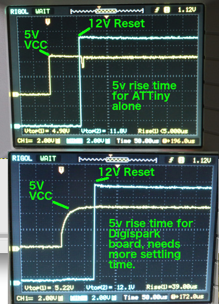
I think the next step is to add say 50uS to the delay between applying vcc and 12v.
If I get time later today I'll try it:

Image

void vcc_on() {
// Enter High-voltage Serial programming mode
digitalWrite(VCC, HIGH); // Apply VCC to start programming process
delayMicroseconds(20); // TRY 50-70uS HERE ???
digitalWrite(RST, LOW); //Turn on 12v
delayMicroseconds(10);
pinMode(DATAIN, INPUT); //Release DATAIN
delayMicroseconds(300);
}

Another version (there are many, all very similar) suggests that an active 12v via a PNP to pos is more reliable than the current 1k pullup to 12v, I will try that too, though that will take a bit longer.
I've since checked out several of these very similar fuse-blower projects, and they all mention weirdness and fuse miss-reads!


EDIT:
Eureka!!!

Thats it chaps. By allowing a bit more 'setting time' before turning on the 12v programming voltage,
all my 'suspect' DigiSparks program perfectly. That includes the 'bink_p5' ones and a couple of '2+1 encoder' ones. I will upload the amended sketch to post #1.

EDIT: Yep that appears to be it. I have 22 DigiSparks here on my bench, some new ones that I've just unpacked, some I've loaded with either 'blink_p5' or the 2+1 encoder, and some with random project sketches on them.

ALL now behave perfectly. The P5 switch to enable the elevon mixer on the 2+1 works fine. They all load blinky ok, and after setting P5 to I/O they all blink P5 ok. After setting P5 back to 'reset' they all reprogram ok.

I'm quite relieved after everyone had hoped to join in the fun and had no success. Please try the amended sketch & let us know how it goes, I hope you'll find its fine now Image

Not sure if I made the operation clear - it reads the fuses, waits 10 seconds, writes 'P5=reset', waits 10 seconds, writes 'P5=I/O' then halts. Just unplug when the DigiSpark is showing the fuse-state you need.

Cheers
Phil
User avatar
tiptipflyer
Posts: 393
Joined: 16 Feb 2018, 22:49
Location: Germany

Re: DigiSpark with 6 input/output pins, homebrew fuse-programmer

Post by tiptipflyer »

Another Eureka from here,

thank you very much Phil, your help is highly appreciated.

Now all three versions of the Digispark work as supposed to. The display changes from DF to 5F as it should and all versions work as expected.
I tried a bigger sketch for a S/C transmitter with separate throttle button, low voltage alert, motor LED etc, no problems.
Also tried a sketch for a two channel proportional transmitter with low voltage alert, inactivity buzzer, S/C button, servo reverse, etc, also no problems.

Cheers
Frank
Last edited by tiptipflyer on 06 May 2019, 08:20, edited 2 times in total.
Martin
Posts: 744
Joined: 16 Feb 2018, 14:11
Location: Warwickshire

Re: DigiSpark with 6 input/output pins, homebrew fuse-programmer

Post by Martin »

Mine's also working with a longer delay. Thanks.

By the way, I recommend putting something like this right at the start of your setup() function. That way, you get something on the display even if no DigiSpark is present or for some reason not responding - it gives you some confidence that at least the sketch is running, and the display working.

Code: Select all

void setup() {
  // Display something to prove that the OLED is working
  u8g.firstPage();
  do {
    u8g.setFont(u8g_font_6x10);
    u8g.drawStr( 0, 20,  "  Phil_G's ATtiny85");
    u8g.drawStr( 0, 40,  "   Fuse programmer");
  } while ( u8g.nextPage() );
  
  // Set up control lines for HV parallel programming
  pinMode(VCC, OUTPUT);
  pinMode(RST, OUTPUT);
  pinMode(DATAOUT, OUTPUT);
  pinMode(INSTOUT, OUTPUT);
  pinMode(CLKOUT, OUTPUT);
  pinMode(DATAIN, OUTPUT);  // configured as input when in programming mode
  
Everything before the setup() function after the while(); statement 7 lines into the setup() function is unmodified.
User avatar
tiptipflyer
Posts: 393
Joined: 16 Feb 2018, 22:49
Location: Germany

Re: DigiSpark with 6 input/output pins, homebrew fuse-programmer

Post by tiptipflyer »

Hi Phil,
this morning, with the help of this great tool, I added another function to my Citizenship replica transmitter.
It now has a motor LED on P5 in addition to the other features.
So it is the first time I tried a real transmitter with a fully loaded Digispark:
P0=PPM, P1=S/C button, P2=buzzer, P3=throttle button, P4=voltage alert, P5=motor LED.
Works great. Thank you Phil for another great project.
CitizenShip7.JPG
Cheers
Frank
User avatar
Phil_G
Posts: 597
Joined: 15 Feb 2018, 23:32
Contact:

Re: DigiSpark with 6 input/output pins, homebrew fuse-programmer

Post by Phil_G »

Thanks lads, relieved to hear they're all working now Image

Thanks both for your perseverance, for anyone else fancying a go - and it is a really useful tool if you like DigiSparks - the sketch in the opening post is updated with the timing mod and a variation of Martin's 'intro' suggestion (go on, try it!), update is in post #1 :D


IMG_5245[1].JPG


Heres the battery holder and 12v battery I used, from Component Shop:

A23 12v Battery
Battery holder

The battery box is permanently wired through a momentary push-to-make button, so no on-off switch is needed. I've been using quite a few DigiSparks lately and the fuse programmer has really been earning its keep Image

Cheers
Phil
IMG_20190425_235939_361.JPG
IMG_20190426_000149_599.JPG
User avatar
tiptipflyer
Posts: 393
Joined: 16 Feb 2018, 22:49
Location: Germany

Re: DigiSpark with 6 input/output pins, homebrew fuse-programmer

Post by tiptipflyer »

I did a 3D-printed case for the fuse programmer.
I am still waiting for the battery holder from China.
It is working great now, no problems anymore.
Thanks Phil.
SAM_3768.JPG
Cheers
Frank
User avatar
tiptipflyer
Posts: 393
Joined: 16 Feb 2018, 22:49
Location: Germany

Re: DigiSpark with 6 input/output pins, homebrew fuse-programmer

Post by tiptipflyer »

Phil_G wrote: 16 May 2019, 19:54 Hows your 12v battery lasting Frank?
Mine is flat already, its down to 9v on load after only a couple of weeks use!
I'm surprised as its a genuine Duracell, I expected it to last forever :D
The battery has got too low to put the DigiSpark in HV programming mode so I've had to go back to the 3S lipo!
Cheers
Phil
My battery was good only for about three to four conversions. Then the voltage was too low to let it work anymore. Therefore I still have the connector for a three cell lipo, to help out.
But I used cheap China batteries.
Cheers
Frank
MaxZ
Posts: 330
Joined: 31 Jan 2019, 11:48
Location: Boskoop, Netherlands

Re: DigiSpark with 6 input/output pins, homebrew fuse-programmer

Post by MaxZ »

Hi all,
I have ordered some Digisparks, and I may soon need a device like this. But eehhh, pardon my ignorance, what is the advantage of using zero ohm links over a good old wire link? I had never heard of the beasties and I had to look up what they are, turns out they are just what the name says, but (according to Wikipedia) are used to facilitate installation by a regular component placement machine. So, can I just use a piece of wire instead?

Cheers,
Max.
Martin
Posts: 744
Joined: 16 Feb 2018, 14:11
Location: Warwickshire

Re: DigiSpark with 6 input/output pins, homebrew fuse-programmer

Post by Martin »

Yes of course. As you said, standard auto-place machines are able to handle standard resistors (which come held together by two paper tapes on their lead ends) so it's easier to make zero ohm links with the same form factor.

You can also get zero-ohm links in surface mount form: they are often used as option selectors on boards, and you change the option by moving the link to a different position, or just removing it from the board completely. For home-brew you can usually just bridge the pads with a blob of solder, but as with the wired through hole auto placers, it's easier for the computer/robot assembling the board to just place a "resistor" that happens to have a resistance of zero.

Wire links are what I used on my build of Phil's fuse programmer.
MaxZ
Posts: 330
Joined: 31 Jan 2019, 11:48
Location: Boskoop, Netherlands

Re: DigiSpark with 6 input/output pins, homebrew fuse-programmer

Post by MaxZ »

Hi Phil,

Did you ever do a veroboard layout for the fuse programmer? I have tried to copy it off the pictures in the opening post, and reproduce the schematic from that, but I am getting some weird results (weird for me), and I would like to check those.

For instance, the GND's of the Nano and the Digispark are linked and connected to pin D2 on the Nano, and I fail to see how this could power the Nano.
Then, the Vin on the Digispark is not connected to anything as far as I can see, and the 5V is connected to D6 on the Nano. I can see how this can power the Digispark with appropriate programming of the Nano.
And if I am seeing this correctly, the minus of the 12V battery is only connected to the emitter of the transistor.

Cheers,
Max.
Post Reply