I posted about this in another forum, RC Groups. Someone there pointed me in your direction and said there may be some interest in my little project.
So I coded up an Arduino to mimic one of the more complex set-ups with rudder, kick up elevator and quick blip to toggle the motor on and off - but I figured we needed menus to set-up the servo centre positions and amount of throws, so I added an LCD screen with a small joystick to navigate the menus and edit the values. And I added some other modern conveniences like multiple model memories, a countdown timer with a bleep countdown for the motor stopping, motor soft start and so on.
We've flown his Gasser using my 'single channel' transmitter as a buddy box slave into his transmitter, so he could take over and save the model if something went wrong. It was fairly successful but he needs to make some adjustments to the motor thrust line and move the centre of gravity before the next test.
So, as I was getting impatient, I dragged my old Veron Cardinal (diesel powered, free flight) down from the loft and converted it to radio control electric power. I fitted some Corona gear to it as the only futaba-shaped module I have is an old Corona one. (I have lots of JR/Turnigy/Taranis sized modules, so the next single channel I build will be to fit those).
Anyway, I test flew the Cardinal last Friday morning, early when it was calm, and it worked great! I messed up the controlling on my first ever go at single channel and landed in a cornfield, but with no damage. Then I had about six more flights and landed on our (small) runway one time but got fairly close by on the other attempts. Great fun.
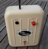
As you can see, it's a 3D printed case and it uses an Arduino Pro Mini to do most everything. I thought about fitting a LiPo or LiFe battery, but worried about how my old pal would charge it and balance the cells - so I ended up with a 6-cell NiMH pack. I fitted a dropper resistor and protection diode so he can charge it with one of his existing Futaba chargers, into a normal Futaba transmitter charging socket.
If anyone here is interested, I'm happy to share the code, the wiring diagrams, the 3D-printer designs and so on. The parts such as the LCD, the joystick and the buzzer are all common parts on Ebay that cost just a pound or three each.
Re: Yet another single channel Arduino project
Postby jackdaw » Tue Aug 04, 2015 9:04 am
Welcome to 'nostalgia corner' on 'tinternet. I'm sure the other members of the forum, especially Phil (who developed the original SC encoder and the Arduino follow on), would be interested in a full 'blow by blow' description of the system. Look foward to a good read.
(ceptimus - not a transformers fan by any chance?)
Re: Yet another single channel Arduino project
Postby Phil_G » Tue Aug 04, 2015 9:15 am
Hi Martin and welcome to the S/C forum
Cheers
Phil
Re: Yet another single channel Arduino project
Postby jackdaw » Tue Aug 04, 2015 9:18 am
Done a search, this your site? http://ceptimus.co.uk/?cat=2
Re: Yet another single channel Arduino project
Postby tiptipflyer » Tue Aug 04, 2015 10:26 am
Hi "ceptimus",
welcome here, that is realy an interesting project. I would love to have a look on your code and the wiring diagrams. To see more about the making of the 3D printed case would also be great. Sometime in the future we will be able to copy the old trasmitter cases simply by using a 3D printer. Thats all very interesting stuff.
Cheers
Frank
Re: Yet another single channel Arduino project
Postby ceptimus » Tue Aug 04, 2015 11:38 am
Thanks guys.
I'm working on a circuit schematic now (I just had some scraps of paper with scribblings) I'll post it all in the next day or so
Re: Yet another single channel Arduino project
Postby kkphantom » Tue Aug 04, 2015 12:55 pm
Could you programme it so that after about 250 inputs it stops working like a rubber driven escapement?
Re: Yet another single channel Arduino project
Postby ceptimus » Tue Aug 04, 2015 2:14 pm
Here's the circuit schematic.
Ron pointed out that I'd labelled the digital pins just 11, 12, and it was unclear whether I meant D11, or pin 11 of the package. I've altered the diagram now to include the Ds, but if the old version in still in your browser cache you might not see them. If you're not seeing the Ds on the diagram press Ctrl-F5 to refresh your browser cache.
It probably looks like a mistake that I've got D4, D5, D6 and D7 going to the same-named pins on the LCD but in the reverse order. The diagram is right though, it's just a coincidence that it ended up that way. The pins on the LCD module aren't actually labelled (at least mine weren't) but I've drawn them out in the correct order to match an actual LCD, looking at the front (display) side. The four unused LCD pins are named D0, D1, D2 and D3 in the LCD documentation.
Re: Yet another single channel Arduino project
Postby tiptipflyer » Tue Aug 04, 2015 3:02 pm
Thank you ceptimus, for your code and the schematics,
that will give me hours of thinking. Very interesting to see another way of doing it, different from Phils method, which I can partly understand. I am not a programmer,. just an ordinary modeller and I needed weeks and months to understand about half of Phils code. Maybe I can understand half of your code by christmas.
Nevertheless I appreciate all new inputs.
All the best
Frank
Re: Yet another single channel Arduino project
Postby ceptimus » Tue Aug 04, 2015 3:48 pm
Thanks Frank!
You don't have to understand the code to use it! For example, on this project I didn't bother to write my own LCD driving code - I just used the code supplied as part of the Arduino library.
If anyone wants to build one, providing they have some experience with Arduinos and are okay at soldering they shouldn't have too much trouble. If they don't have access to a 3D printer to print the case, I could print some for them (or they could always build a 'traditional' case from balsa or plywood or whatever they're happy working with).
--------------------------------------------- P2 -------------------------------------------------------
Re: Yet another single channel Arduino project
Postby jackdaw » Tue Aug 04, 2015 5:01 pm
Maplins would probably have a case that would be suitable (size of your case?), although 'hack' modules seem to be the favourite RF package. Any links you could provide to the parts you used, ie LCD, joystick, etc , would be useful especialy to those (I'm talking about me here) suffering from the effects of advancing years!
Re: Yet another single channel Arduino project
Postby ceptimus » Tue Aug 04, 2015 5:22 pm
Okay, here are a few pics of the transmitter.
Re: Yet another single channel Arduino project
Postby ceptimus » Tue Aug 04, 2015 6:12 pm
The way the display works is as follows:
First, let's assume that when you switch on, the correct model is already selected (it remembers which one you selected last time, even when it's off).
The top line of the display will be showing "Motor time: 5:00" (assuming you have it set for five minutes - again it remembers the previous setting even when it's switched off).
...and the bottom line cycles through three different pieces of information - each one is displayed for about a second and a half:
" 2 Gasser " this shows the model memory selected (Number 2 here - there are 15 available) and the model name, which can be up to 13 characters long.
"Press joy starts" this is an instruction to remind you how to start the motor - you press the joystick in - as well as moving up/down and left right, you can also push it like a button.
"Battery 7.9V" this shows the current state of the battery. If the battery is low, it changes to, say, "Battery low 6.5V" and the buzzer beeps every second.
Now before you start the motor, you can move the joystick to the right to increase the motor run time in 10-second increments, or to the left to decrease it by the same.
When you press the joystick in, the motor runs up to speed and the top line changes to showing "Remaining 4:59" or whatever, counting down the seconds. It gives you a warning beep at 30 seconds remaining, then another at 10 seconds, and a 5-bleep countdown and long final bleep (like the time pips on the radio) for the last 5 seconds before stopping the motor. The "Press joy starts" thing on the bottom line changes to "Press joy stops", of course.
At any time when the motor is running, you can press the joystick again to stop the motor and return to the initial 'stopped' state. You can use this as a kind of 'emergency stop', as you have the normal facility to toggle motor between paused and running with a 'quick blip' on the main button.
Whether the motor is running or not, the main button controls the rudder and elevator. Press and hold for right. Press, release, press and hold for left. Press twice then press and hold for kick up elevator.
If the motor has been started by using the joystick "button" then it can be (optionally, see later) toggled between running and paused by a quick blip on the main button. When the motor has been paused this way, the "Remaining" display changes to "Paused" and the timer stops counting down until you start the motor again.
The up/down direction on the joystick lets you scroll through all the menus to adjust parameters, but I'll leave that for another post as this one is long enough already.
Re: Yet another single channel Arduino project
Postby ronstv » Tue Aug 04, 2015 6:45 pm
Hi Martin,
Im just ordering the parts now, Ive found a suitable lcd module but I'm a bit unsure about what joystick to use,
Do you have an UK eBay link you can suggest?
Ive successfully programmed a Nano with the sketch so thats one job done
Thanks
Ron
Re: Yet another single channel Arduino project
Postby ceptimus » Tue Aug 04, 2015 6:54 pm
Okay - on to the menu items.
If you move the joystick down (and release) once you get to the Model selection menu. Then down again for the next menu and so on. You can also scroll up through the menus by using an 'up' movement and release.
I'll list all the menus first, and then describe what they do.
Main display, as described in previous post.
Model selection.
Editing model name.
Copying one model memory to another.
Rudder centre position.
Rudder right position (travel).
Rudder left position.
Elevator centre position.
Elevator up position.
Elevator down position! (see below)
Motor off setting.
Motor on setting (allows motor to run at desired speed - say 55% or whatever).
Motor soft start time (lets motor run up to speed gradually instead of starting with a jerk).
Button speed (allows you to set the 'escapement speed' to suit your personal preference).
Motor control by quick blip? (you can set this to 'no' if you don't want to use quick-blip motor control).
Joystick mode! (see below)
Low battery alarm limit.
In the model select menu, you can see all the available models by using left/right on the joystick. When the one you want is displayed, press the joystick in (its button mode) to select that model.
In the edit name menu, pressing the joystick in allows editing to begin, then left/right on the joystick selects a character position within the name and up/down changes the character. When you've finished editing the name you press the joystick in again. With all these joystick functions, there is an auto-repeat that gradually speeds up if you hold the joystick over for a long time - so you could do three quick up presses and releases to change a G to a J, but if you wanted to change it to a Z, you'd probably hold the joystick up and watch it change rapidly till you got close.
The model copying menu uses left/right to select a destination model memory where you want to copy to. Pressing the joystick in copies the current settings to that model memory, and selects the new copy as the current model.
The 'position' menus all display the current microsecond pulse interval for that channel. In real life you don't take much notice of the numbers displayed - say you're setting the rudder right position: then you would press and hold the main control button to move the rudder on the model; then use the joystick to scroll to the 'rudder right menu and then left and right on the joystick till the rudder is in the position you want. When you're setting the centre positions of the rudder or elevator there is no need to use the main control button, of course. With the main control button released you can go to the 'centre' menu items and then use left and right on the joystick and watch the model controls move in real time.
Joystick mode is a little cheat I built in that might be useful for test flying a model that's not yet been trimmed. You set what looks like sensible positions for left/right rudder and up/down elevator. Then enable joystick mode by scrolling to the joystick menu and pressing the joystick in. Then you can fly the model using the joystick. You have proportional control - like with the right stick on a mode 2 proportional set. The main button toggles the motor between the 'off' and 'on' speeds when you're in this mode. It's rather a cheat and only really intended for trimming flights - but it does give you a way to control the model if the centre positions you guessed were wrong, or if you need to use down elevator. It's no substitute for a real proportional set if that's what you want - not least because the cheap joystick isn't particularly linear and has a pretty big 'dead' zone around the centre stick position. Once you've selected joystick mode, then it remains in force till you switch the transmitter off and back on. Originally I had it so that pressing the joystick in again would switch it back off - but I realized that when you're flying this way you're quite likely to press the joystick by accident which would most likely lead to a crash or fly-away unless you quickly realized what had happened.
Re: Yet another single channel Arduino project
Postby ceptimus » Tue Aug 04, 2015 7:00 pm
Hi Ron, that was quick work!ronstv wrote:Hi Martin,
Im just ordering the parts now, Ive found a suitable lcd module but I'm a bit unsure about what joystick to use, Do you have an UK eBay link you can suggest?
Ive successfully programmed a Nano with the sketch so thats one job done
Thanks - Ron
Here's a Hong Kong seller for 99p including shipping! They're even cheaper if you buy two or three at once!
If you don't want to wait, here's a UK supplier, but it costs £2.78
Re: Yet another single channel Arduino project
Postby ronstv » Tue Aug 04, 2015 7:09 pm
Thanks Martin,
A couple of quid is nothing. Ive ordered from the UK seller.
Thats all the bits ordered, Just a case to sort out, I normally use the Maplins MB range.
Ron
Re: Yet another single channel Arduino project
Postby ceptimus » Tue Aug 04, 2015 7:20 pm
If you build one, then, you will want to reset all the model memories to defaults and calibrate the joystick. Power it up and adjust the contrast pot till you can see the display - but the display may be scrolling through all the menus by itself - this is because the joystick hasn't been calibrated yet and the Arduino can't recognize that the joystick is in its centre position.
So power off, link the '9' pin to 'GND' and power back on. The display shows: "Cycle joystick" "Center. Button".
Move the joystick in slow circles at its full travel so the Arduino can read and store the maximum and minimum x and y values. Then release the joystick back to the centre and press the main control button (not the joystick itself). The Arduino then samples and stores the joystick centre position. Now you can power down and remove the '9' to 'GND' link. You shouldn't need to do this again. The joystick settings and the model memories are stored in the EEPROM memory of the Arduino, so even when you modify and upload the program (sketch) the stored values are not affected or lost.
Re: Yet another single channel Arduino project
Postby ceptimus » Tue Aug 04, 2015 7:26 pm
Stay tuned for the 3D printed case info! I'd be happy to print one and send you if you wish. The joystick module is a little tricky to mount - in the 3D print version there is a concave depression inside the front face of the case to match the 'ball' on the joystick, and the mounting legs hold it just the right distance back from the front face.ronstv wrote:Thanks Martin,
A couple of quid is nothing. Ive ordered from the UK seller.
Thats all the bits ordered, Just a case to sort out, I normally use the Maplins MB range.
Ron
If you make a case yourself with a hole to suit the joystick and some pillars to mount the joystick PCB, be warned that the pillars tend to catch against the moving part of the joystick mechanism. I ended up with 'leaning pillars' on the 3D print version! If you're fabricating something yourself it's probably easier to use a spreader plate around the joystick PCB so that the pillars can be further away. Alternatively you could mount the joystick from the back and then just have the front cover fit over it without needing any 'front pillars'.
Re: Yet another single channel Arduino project
Postby ceptimus » Tue Aug 04, 2015 8:07 pm
I'll post the pic of the small vero board layout I used to house the contrast pot, the 'charging circuit', etc. However please feel free to roll your own. This is probably more confusing than helpful. The crosses mark where the tracks (running left to right) were drilled. The box towards the right is the contrast pot, the box next to it is the 10K resistor and the one between that and the diode is the 22K. I didn't actually have any 1/2 watt resistors available so I used three quarter-watt resistors to make one. I can't remember whether I put three 100-ohm resistors in parallel or three 10-ohm resistors in series.
------------------------------------------- P3 ------------------------------------------
Re: Yet another single channel Arduino project
Postby tiptipflyer » Mon Aug 10, 2015 5:36 pm
Hi guys,
today was the time, to test the new single channel Arduino Transmitter in real life (in flight). I had some trouble yesterday evening with my 35MHz version. With the antenna in, everything worked fine, when the antenna was extended to full length, nothing worked anymore, not even the joystick. After checking everything, I found the trouble. The Arduinos do not like a 35MHz antenna close by. When I increased the distance between the Arduino and the antenna and module by one inch, everything was working fine again. I had the same trouble, when I converted a Grundig Variophon 2 reeds transmitter to Arduino some time ago. After re-arranging everything to give more distance between the Arduino and the HF part, everything was working great. No trouble anymore with dozens of flights meanwhile. Instead of re-arranging everything on this S/C transmitter, I installed an Orange Spektrum 2.4 GHz module, which was a lot easier and faster.
Test flight today was great, no problems at all. I was flying the Pageboy and the Schoolboy several times without any troubles. I could even trim the center position of the rudder in flight with the joystick; great feature. I have presently 10 models in the memory and more are to come.
In the futrure I will build a second version on 35MHz again and will arrange all parts better, so it will work without any disturbances.
By the way, I use only the cheap nano and pro mini Arduinos and I have converted more than 20 transmitters with Arduinos without having any sort of trouble. No one did fail until now and they are all working fine.
So guys, keep building it is worth it.
Cheers
Frank
Re: Yet another single channel Arduino project
Postby ceptimus » Mon Aug 10, 2015 7:04 pm
Great news on the successful flights Frank. Well done!
I guess RF around 35 MHz is likely to interfere with Arduinos as it's fairly close to double the clock frequency (16 MHz) that the Arduino operates at.
Have you ever tried some screening around the Arduino instead of moving it further away? In theory you want a conductive (so metal) container surrounding the thing you want to screen, and it's probably a good idea to 'earth' that container to the negative battery terminal. You really want to screen as much of the wiring as possible too.
It's easier when you plan it during construction - you can make a tin plate box or similar for the Arduino and use screened cable for the wiring.
Once it's already built it's not so easy, but you might be able to wrap the Arduino in some cooking foil (wrap it in plastic first so that the foil can't short out the connections). And just getting a long wire connected to the battery ground and winding it in spirals around the other wires helps to screen them - even though there are huge gaps between successive turns of the spiral it can still provide a useful screening effect.
The other thing that might help would be some ferrite rings - any longish wires leading from the Arduino away to other things you loop a few turns through a ferrite ring. Often you can share one ferrite ring ring for most of the wires, although theoretically it's best to have separate small ferrite rings for each cable. The ferrite rings should be close to the thing you're trying to protect from interference - so you put them near the 'Arduino end' of the wires.
Re: Yet another single channel Arduino project
Postby tiptipflyer » Sat Jan 07, 2017 11:53 am
Hi guys,
the next transmitter is ready to use. It will be a long testflight session, I have already 15 models stored on the transmitter memory. I took all the values from my previous tranny, but they need to be confirmed in real flight of course (check here: viewtopic.php?f=6&t=396&start=36). When this is done, I will upgrade my older transmitter to the latest software version.
The problem, I had with my old transmitter regarding 35MHz is solved, I just had to use a shielded cable from the S/C button to the Arduino, from now on, no interferences anymore. The old tranny has now both modules on board, 35MHz and 2.4GHz, selectable by a toggle switch.
Cheers
Frank
Re: Yet another single channel Arduino project
Postby Phil_G » Sat Jan 07, 2017 15:22 pm
Here's mine under construction. I made an all-in-one PCB for mine: