The idea is to give you something to start with and play around....and if something goes wrong just extract the .zip file again and continue!
The board is one of my Basic Test Board that replace in some how a breadboard/stripboard and this one in particular can work both as a 6 ch nRF24L01 receiver, as PPM RF-module - viewtopic.php?f=42&t=1703 - and much more. There is direct access to A4 & A5 on the board suitable for a display .... or just inputs for a simple encoder with 2 channels.
The difference between this board and my earlier ones is that it has reverse polarity protection and a voltage regulator set to 3,3v but the pin headers still keeps +Batt which if you stay below 12 volt would make the board almost bulletproof...I said almost and allows to do some mistake before you are going to verify that different components contain different amount of blue smoke! To be able to do this I'm using an external 8 MHz X-stal.
I'm going to share here a project suitable for those of you that are looking for/ have the ambition to look into designing circuit boards and have them manufactured by a third part like JLCPCB.
For whatever reason I chose to learn KiCad followed by having JLCPCB to manufacture my board and I have been very pleased with the result so...
With this approach my projects really took off but there sure was a bit of take off distance requiring some efforts not least to watch a few tutorial on YouTube and here I was recommence tutorials by "Phil's Labs" followed by some practising on the computer, nothing of all of this is rocket science but it sure requires some dedication so it's up to you if you are ready to make the effort!
With KiCad everything starts with the design of the schematics and it is where most people struggle so take your time and really learn to use flags instead of drawing route tracks.
A proper drawn schematic allows to make easily changes and amendment like adding more and more features like reverse polarity protection mosfets or inductors on the supply regulator etc. and when letting JLCPCB manufacture the boards to leave behind not only through-hole ATmega towards smd like resistors, caps, transistors and even sounders as they are only cents from JLCPCB and what used to take hours if not even days to mount on stripboards now arrives ready assembled, at a cost less than you can buy the components after a struggle to find them all and order from different suppliers. With this in mind and that most components are so compact (and cheap), more and more components/features can be added and integrate it all in one board with size and shape that you have full control off and it's professionally manufactured by any means and look.
- This schematic could sure be better not least with more appropriate notes if your memory is like mine, very good but short!
To work as a receiver just download the sketch from Phil_G nRF24 project, it will not be as tiny as some of my regular Rx but works as good.
If used as a PPM Tx RF Module just solder on a nRF24 module with PA and shielded and connect the PPM signal to D8 after installed the RF module sketch and you are ready to go. The programming is done like for most of my projects if I'm not using ICSP port.
For simplicity a commercial nRF24 module is piggy back to this board.
- This picture is from a previous version but as soon I get the new revised boards I will update with new/more pictures to show different versions and options.
I will later share with you some basic sketches and more option what can be done with this Basic Module.
At the completion of the schematics you are just a click away to start laying out the circuit board itself but not before a few setups like width of route tracks and amount of layers, there was a time that more than 2 layers would have become extremely complicated and expensive but not so anymore and this open for neater a smaller boards, the board I show here is a 4 layer boards where the bottom layer is almost just a GND plane.
KiCad will show which points needs to be connected and where the path could be routed ,..and if everything else fails you pop in a via and go to another layer to continue!
All of this trivialities are very well described in "Phil Lab's" tutorial on YouTube.
PS:
I'm still using KiCad 5.1.12 but they are now at version 7.1 which means you are able to open the files but they will be saved in the newer version as well I'm still using Arduino 1.8.19
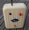
What I'm showing here is the exact module just received from JLCPCB ordered on the files that are here included.
- The actual board as it arrived from JLCPCB
- The boards with a few options of nRF24 modules
- ...and here the nRF24 modules soldered on
pinMode(failSafePin, INPUT_PULLUP); // momentarily link to gnd to set failsafe
pinMode(A0, OUTPUT); // led
pinMode(A1, OUTPUT); // led
digitalWrite(A0, 0); // 5v led pos
digitalWrite(A1, 0); // led ground - if second LED doesn't light up exchange 0 with 1 eg. (A1, 1)
To use the module as a RF module you have to wait a little longer for that sketch and the reason is that this module have the 328 running at 8 MHz.