Hi Max,
the capacitor in the Rx is a standard 100nF plus a 100µF 10V elko on the other side.
The brushed motor in the Pageboy uses 3 capacitors 47nF each between the terminals and from the terminals to the metal case. No problem with noise.
Cheers
Frank
Frequency hopping experiments on the NRF24
-
tiptipflyer
- Posts: 393
- Joined: 16 Feb 2018, 22:49
- Location: Germany
-
Phil_G

- Posts: 603
- Joined: 15 Feb 2018, 23:32
- Contact:
Re: Frequency hopping experiments on the NRF24
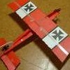
Fantastic Frank, very well done indeedtiptipflyer wrote: ↑09 Jun 2020, 13:55 .... all was working well and today was flighttest-time. Using my old Pageboy, I had several wonderful flights with the NRF24 S/C system. All was working great, no problems, no glitches, no range problems.
Lockdown has some benefits
Max, yes the D9-D13 connections are straight through and you can wire them directly, though I find the adapter connections are neater, especially the folded-over version
I always use the ingrained BT colours, old habits die hard...
blue (D9), orange (D10), green (D11), brown (D12), slate (D13)...
and red & black for power:
Theres no need to delete it Max, just ignore it
-
tiptipflyer
- Posts: 393
- Joined: 16 Feb 2018, 22:49
- Location: Germany
Re: Frequency hopping experiments on the NRF24
The next transmitter is ready, this time a four channel proportional one.
It is an old, much used robbe Economic set, which I converted using the NRF24 high power unit.
To power the unit I used a small 3.3V step-down converter. This one uses the same 3.3V chip than the much bigger adapter and is a lot easier to fit.
I used Phils propo sketch and removed all extras I do not need, leaving just the basic four channel unit with throttle lock and servo reverse as the only extras.
Flight-test was this morning, no problems. Works fine, no glitches , no range issues, all great.
I also tested the Futaba S/C replica using this time the low power unit.
After the Pageboy was about 50m away and climbing, the trouble started. I managed to come down without any damage, but the low power unit is not suitable for flying.
After reinstalling the high power NRF24, the flight was continued without any problems.
Cheers
Frank
It is an old, much used robbe Economic set, which I converted using the NRF24 high power unit.
To power the unit I used a small 3.3V step-down converter. This one uses the same 3.3V chip than the much bigger adapter and is a lot easier to fit.
I used Phils propo sketch and removed all extras I do not need, leaving just the basic four channel unit with throttle lock and servo reverse as the only extras.
I also tested the Futaba S/C replica using this time the low power unit.
After the Pageboy was about 50m away and climbing, the trouble started. I managed to come down without any damage, but the low power unit is not suitable for flying.
After reinstalling the high power NRF24, the flight was continued without any problems.
Cheers
Frank
-
Wayne_H

- Posts: 811
- Joined: 17 Feb 2018, 05:26
- Location: Temora, NSW. Australia
- Contact:
Re: Frequency hopping experiments on the NRF24
Well done Frank (yet again
  )
)
I have to hand it to you - you are a "machine", and an inspiration, when it comes to turning out these projects. Keep it up mate!!!
 (yet again
 I have to hand it to you - you are a "machine", and an inspiration, when it comes to turning out these projects. Keep it up mate!!!
Cheers,
Wayne
Once a Retrobate, always a Retrobate............
Wayne
Once a Retrobate, always a Retrobate............
-
MaxZ
- Posts: 330
- Joined: 31 Jan 2019, 11:48
- Location: Boskoop, Netherlands
Re: Frequency hopping experiments on the NRF24
Congratulations with another successful project Frank!
I am still working on mine, but I am waiting for the missing parts which seem to be lost in the sky between China and The Netherlands
Mine will be a 2-channel version, but all the electronics and code are there to expand it to a full 4-channel propo Tx, all I will need to do is install a second stick unit and a third rate pot (and stuff it in a larger box..).
Where did you get the nice little 3v3 converter? It would make sharing a Nano, an NRF unit and a converter in the compartment ahead of the stick unit a bit easier......
Cheers,
Max.
I am still working on mine, but I am waiting for the missing parts which seem to be lost in the sky between China and The Netherlands
Mine will be a 2-channel version, but all the electronics and code are there to expand it to a full 4-channel propo Tx, all I will need to do is install a second stick unit and a third rate pot (and stuff it in a larger box..).
Where did you get the nice little 3v3 converter? It would make sharing a Nano, an NRF unit and a converter in the compartment ahead of the stick unit a bit easier......
Max.
Last edited by MaxZ on 16 Jun 2020, 08:11, edited 1 time in total.
-
tiptipflyer
- Posts: 393
- Joined: 16 Feb 2018, 22:49
- Location: Germany
Re: Frequency hopping experiments on the NRF24
Thanks guys.
The 3.3V step down converter are available all over the place, here is one example:
https://www.ebay.de/itm/2-5-10PCS-AMS11 ... SwQZFd~dBa
If you buy 10, they cost less then €0,34 each.
Frank
The 3.3V step down converter are available all over the place, here is one example:
https://www.ebay.de/itm/2-5-10PCS-AMS11 ... SwQZFd~dBa
If you buy 10, they cost less then €0,34 each.
-
Phil_G
- Posts: 603
- Joined: 15 Feb 2018, 23:32
- Contact:
Re: Frequency hopping experiments on the NRF24
Fantastic Frank, very satisfying isnt it?
50m with the low power module is pretty good I thought!
Thank you for your encouragement with the project, and for the regulator idea, I do have some but it didnt occur to me to use them with the transmit module! Its a great idea as the 0v and 3v3 pins align, so the regulator can sit rigidly on two header pins. I must remember to solder the NRF wires first though, they're harder to get to once the reg is in place.
My last batch of regs arrived as a 'biscuit' - quite impressed that they stayed that way through the post!
As you can see they're a quarter of the size of the standard regulator:
This seems to be a really stable, repeatable project, I've made loads of them now and they all just work straight away. I just made another S/C emulation setup using a 'Strong' and Franks regulator idea, which makes a really neat job:
I made the NRF connections exactly as the diagrams in previous posts with a 'sideways' servo plug:
...the only untidy bit was tagging on the neg wire to the NRF corner terminal, which is one of the two standoff pins for the regulator:
A few have queried the speed of the link & re-link which I emphasised in the last video
Whilst Frsky is much quicker than Spektrum, it still takes a second or so to re-link. The reason the homebrew NRF is instant is that here is no handshake, GUIDs are already stored and hopping schemes are already known, theres no memory-match exchange, etc... This is one of the reasons I'm not tempted to add a bind handshake sequence, I like having it hard-coded, I like the fact that I can have two transmitters with the same configuration and switch transmitters in mid-flight without even the slightest latency
Even an overlap doesnt bother it - whilst both are 'on' the receiver will choose one tx or the other, until either tx is switched off, nothing catches fire, the sky doesnt fall, theres no magic smoke...
-
iflylilplanes
- Posts: 183
- Joined: 13 Mar 2018, 03:26
- Location: Sydney Australia
- Contact:
Re: Frequency hopping experiments on the NRF24
Hey Phil, How much for a TX and RX without batteries and servos to Australia? just wondering, should fit inside an OS Pixie case with room to spare.
Cheers,
Dave
Cheers,
Dave
Cheers,
Dave
Dave
-
tiptipflyer
- Posts: 393
- Joined: 16 Feb 2018, 22:49
- Location: Germany
Re: Frequency hopping experiments on the NRF24
Well Guys,
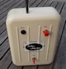
the next conversion is ready (at least the Tx is). I am working on my Tamiya Wild Willy, it should be already a retro model, it is at least 35 years old and had not been used for at least 25 years.
The old car radio got its conversion to the nrf24 module as a two channel propo transmitter. The original reverse switches on the left and the throttle trim pot are still all working with the new setup. One of the other trim pots is used to adjust the battrery meter.
Works great.
I know, the Willy needs a carwash.
Cheers
Frank
the next conversion is ready (at least the Tx is). I am working on my Tamiya Wild Willy, it should be already a retro model, it is at least 35 years old and had not been used for at least 25 years.
The old car radio got its conversion to the nrf24 module as a two channel propo transmitter. The original reverse switches on the left and the throttle trim pot are still all working with the new setup. One of the other trim pots is used to adjust the battrery meter.
Works great.
Cheers
Frank
-
Phil_G
- Posts: 603
- Joined: 15 Feb 2018, 23:32
- Contact:
Re: Frequency hopping experiments on the NRF24
Yours are much neater than either of my car sets Frank
Dont do what I did - I forgot to set the default failsafe to 1500 and when I switched off, the car threw itself backwards across the shed into one of my shiny guitars 
I've just done a set of boards for Shaun so he'll be joining the nrf club soon
Next I'll do the Reeduino version, and I have a 40mhz OS Pixie Mk2, I might convert that next for a 3/4 Wizard of Oz or something. Conversions are so cheap now
-----------------------------------------------------oooOOOooo -----------------------------------------------------
Demo: Simultaneous use of a common configuration
Remember the furore when Futaba accidentally released a few transmitters with the same GUID? That was a Bad Thing, but doing the same thing intentionally can be useful within your own fleet - it means you can fly any model with any of your transmitters, and the instant linkup means you can even change transmitters mid-flight. But what happens if there is an overlap, where two transmitters with the same configuration are on at the same time? Whilst it maintains synchronisation, the receiver is unaffected by the second transmitter. Inevitably at some point a few packets will be missed are it will re-sync, at which point its a 50:50 chance of which transmitter it will lock to, and you wouldnt intentionally stretch the period when both transmitters are on. But for a brief overlap, there is no conflict, no failsafe, no magic smoke, just well-behaved continuity.
Note that all the transmitters in the video have been deliberately given the same configuration - ie the identical GUID and hopping scheme. No-one else will have this configuration, its unique to me and no-one else with a similar set can interfere with mine, nor me with theirs. The ability to swap my transmitters relies on them all deliberately sharing my personal GUID and hopping scheme.
Whilst I might choose to set up my transmitters with either a common configuration like this, or have them all different - yours can also be all the same or all different, BUT all of your configurations will of course be different to mine. This is why the actual config I use is never included in posted code!
Cheers
Phil
Edit: had a chat with Mike K this afternoon, he was tickled that I'd gone completely in the opposite direction to model match, which has the express purpose of preventing what we're doing here!
Dont do what I did - I forgot to set the default failsafe to 1500 and when I switched off, the car threw itself backwards across the shed into one of my shiny guitars
I've just done a set of boards for Shaun so he'll be joining the nrf club soon
Next I'll do the Reeduino version, and I have a 40mhz OS Pixie Mk2, I might convert that next for a 3/4 Wizard of Oz or something. Conversions are so cheap now
-----------------------------------------------------oooOOOooo -----------------------------------------------------
Demo: Simultaneous use of a common configuration
Remember the furore when Futaba accidentally released a few transmitters with the same GUID? That was a Bad Thing, but doing the same thing intentionally can be useful within your own fleet - it means you can fly any model with any of your transmitters, and the instant linkup means you can even change transmitters mid-flight. But what happens if there is an overlap, where two transmitters with the same configuration are on at the same time? Whilst it maintains synchronisation, the receiver is unaffected by the second transmitter. Inevitably at some point a few packets will be missed are it will re-sync, at which point its a 50:50 chance of which transmitter it will lock to, and you wouldnt intentionally stretch the period when both transmitters are on. But for a brief overlap, there is no conflict, no failsafe, no magic smoke, just well-behaved continuity.
Note that all the transmitters in the video have been deliberately given the same configuration - ie the identical GUID and hopping scheme. No-one else will have this configuration, its unique to me and no-one else with a similar set can interfere with mine, nor me with theirs. The ability to swap my transmitters relies on them all deliberately sharing my personal GUID and hopping scheme.
Whilst I might choose to set up my transmitters with either a common configuration like this, or have them all different - yours can also be all the same or all different, BUT all of your configurations will of course be different to mine. This is why the actual config I use is never included in posted code!
Cheers
Phil
Edit: had a chat with Mike K this afternoon, he was tickled that I'd gone completely in the opposite direction to model match, which has the express purpose of preventing what we're doing here!