Rehaton 10
-
stuart mackay
- Posts: 587
- Joined: 01 Mar 2018, 10:38
- Location: Swaffham, Norfolk
- Contact:
Rehaton 10
Any of our German friends shed some more light on the Rehaton?
Last edited by stuart mackay on 06 Nov 2024, 14:39, edited 1 time in total.
-
Phil_G

- Posts: 783
- Joined: 15 Feb 2018, 23:32
- Contact:
Re: Rehaton 10
Frank built a Rehaton replica a while ago Stu...
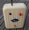
The one on the left looks unusual, just two vertical toggles which conventionally would be throttle & elevator trim?
Does the 'throttle' toggle actually go left-right, maybe is was made for a left-handed flyer?
The one on the left looks unusual, just two vertical toggles which conventionally would be throttle & elevator trim?
Does the 'throttle' toggle actually go left-right, maybe is was made for a left-handed flyer?
-
stuart mackay
- Posts: 587
- Joined: 01 Mar 2018, 10:38
- Location: Swaffham, Norfolk
- Contact:
Re: Rehaton 10
Dunno Phil, I ll let you know when they arrive in Swaffham!
-
tiptipflyer
- Posts: 406
- Joined: 16 Feb 2018, 22:49
- Location: Germany
Re: Rehaton 10
The Rehaton 10 was a home build reeds radio with a maximum of 10 channels very similar to the Multiplex 3x4 radio from a company called Engel.
It was offered in kit form by Reuter, a German company offering kits for several radio sets.
I might have more information and maybe circuit diagrams, if I dig deeper in my shed.
The Rehaton receiver consists of several stages like the Grundig Variophon receivers.
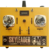
Here are some pictures of my original Reuter Rehaton 10 incl. the receiver (mostly in working condition)
and my two replicas of it.
If you need more information, don´t hesitate to ask.
Frank
It was offered in kit form by Reuter, a German company offering kits for several radio sets.
I might have more information and maybe circuit diagrams, if I dig deeper in my shed.
The Rehaton receiver consists of several stages like the Grundig Variophon receivers.
Here are some pictures of my original Reuter Rehaton 10 incl. the receiver (mostly in working condition)
and my two replicas of it.
Frank
-
Tobe
- Posts: 711
- Joined: 16 Feb 2018, 06:19
- Location: Varberg or Stockholm, Sweden
Re: Rehaton 10
...amazing engineering and the attention to details!
Would be nice, if possible to see the inside of one of the Rx-modules as if it would be reed and not tone there should be a "reed-bank" in each module.
Would be nice, if possible to see the inside of one of the Rx-modules as if it would be reed and not tone there should be a "reed-bank" in each module.
Cheers,
Tobe
Tobe
-
F2B

- Posts: 212
- Joined: 16 Feb 2018, 11:23
- Location: 20 m NE of Amsterdam
Re: Rehaton 10
No, no reeds.
Reuter always used the Schumacher tone filter circuit.
Similar to this circuit, but with 2 filter stages.
Clever use of the transistor as a tuned AC amp and then again as a DC switch.
I used Reuter's pot cores and capacitor sets to build my first RC set from scratch, a 2 channel tone filter unit.
Got it working, though never enough range (being age 17, I had no clue about HF back then).
In hindsight the oscillator probably wasn't feeding enough signal to the power stage...
Hence not driving it into saturation, eventually killing any Class C stage.
I blew up several AF 118 while trying to improve this.
After 3 fly aways I had enough and started on a Classic Custom that ended up with almost the same range...
But then with the telescope antenna all the way in.
A few years back I had the plan for making a 27 MHz receiver with a simulated tone filter bank.
I tweaked an Arduino sketch for a telephone touch pad decoder so it actually responded to the 1080 an 1320 Hz tones.
Then I discovered the HF brick from the Rehaton 10 I have here also didn't work. So the project was grounded....
#include <Goertzel.h>
int sensorPin = 4; //nog checken!!!!!!
const int N = 100; //it is the number of samples code will take y0u can change for sensitivity and can if large it can slow the arduino
const float threshold = 2000; //minimum tone amplitude to be considered we can change it for more senstivity
const float sampling_freq = 8900; //maximum detectable frequency is the sampling rate/2 and arduino uno with 16Mhz can support sampling upto 8900 Hz
float frequency[2]; //make an array for channel frequencies to be detected
int channel;
int ch;
int reset = 0;
void setup(){
pinMode(1, OUTPUT); //initalize blink led to show if any tone is detected
pinMode(2, OUTPUT); //initialize 2 pins as output to show the channel outputs from 2 to number 3
pinMode(3, OUTPUT);
frequency[0]=1080; //just initialize the array with the tone frequencies along with their number
frequency[1]=1320;
}
bool detect_tone(float freq){
Goertzel goertzel = Goertzel(freq, N, sampling_freq); //initialize library function with the given sampling frequency no of samples and target freq
goertzel.sample(sensorPin); //Will take n samples
float magnitude = goertzel.detect(); //check them for target_freq
if(magnitude>threshold) //if you're getting false hits or no hits adjust the threshold
{
return true;
}
else
return false;
}
void loop(){
int i=0;
while(1){
if(detect_tone(frequency) == true){
channel = i;
break;
}
i++;
if(i==3)
i=0;
}
//find the number corresponding to the found channelfrequency
if(channel== 0)
digitalWrite (2,HIGH);
if(channel== 1)
digitalWrite (3,HIGH);
delay (100);
if(detect_tone(frequency) == false)
digitalWrite (2,LOW);
digitalWrite (3,LOW);
}
Reuter always used the Schumacher tone filter circuit.
Similar to this circuit, but with 2 filter stages.
I used Reuter's pot cores and capacitor sets to build my first RC set from scratch, a 2 channel tone filter unit.
Got it working, though never enough range (being age 17, I had no clue about HF back then).
In hindsight the oscillator probably wasn't feeding enough signal to the power stage...
Hence not driving it into saturation, eventually killing any Class C stage.
I blew up several AF 118 while trying to improve this.
After 3 fly aways I had enough and started on a Classic Custom that ended up with almost the same range...
But then with the telescope antenna all the way in.
A few years back I had the plan for making a 27 MHz receiver with a simulated tone filter bank.
I tweaked an Arduino sketch for a telephone touch pad decoder so it actually responded to the 1080 an 1320 Hz tones.
Then I discovered the HF brick from the Rehaton 10 I have here also didn't work. So the project was grounded....
#include <Goertzel.h>
int sensorPin = 4; //nog checken!!!!!!
const int N = 100; //it is the number of samples code will take y0u can change for sensitivity and can if large it can slow the arduino
const float threshold = 2000; //minimum tone amplitude to be considered we can change it for more senstivity
const float sampling_freq = 8900; //maximum detectable frequency is the sampling rate/2 and arduino uno with 16Mhz can support sampling upto 8900 Hz
float frequency[2]; //make an array for channel frequencies to be detected
int channel;
int ch;
int reset = 0;
void setup(){
pinMode(1, OUTPUT); //initalize blink led to show if any tone is detected
pinMode(2, OUTPUT); //initialize 2 pins as output to show the channel outputs from 2 to number 3
pinMode(3, OUTPUT);
frequency[0]=1080; //just initialize the array with the tone frequencies along with their number
frequency[1]=1320;
}
bool detect_tone(float freq){
Goertzel goertzel = Goertzel(freq, N, sampling_freq); //initialize library function with the given sampling frequency no of samples and target freq
goertzel.sample(sensorPin); //Will take n samples
float magnitude = goertzel.detect(); //check them for target_freq
if(magnitude>threshold) //if you're getting false hits or no hits adjust the threshold
{
return true;
}
else
return false;
}
void loop(){
int i=0;
while(1){
if(detect_tone(frequency) == true){
channel = i;
break;
}
i++;
if(i==3)
i=0;
}
//find the number corresponding to the found channelfrequency
if(channel== 0)
digitalWrite (2,HIGH);
if(channel== 1)
digitalWrite (3,HIGH);
delay (100);
if(detect_tone(frequency) == false)
digitalWrite (2,LOW);
digitalWrite (3,LOW);
}
F2B or not to be....
-
Tobe
- Posts: 711
- Joined: 16 Feb 2018, 06:19
- Location: Varberg or Stockholm, Sweden
Re: Rehaton 10
Thank you for this clarification and it's like I thought but was confused by Frank mentioning reeds ... if it would have been reed it sure would have called for an even more clever solution being modular!
Cheers,
Tobe
Tobe
-
Mike_K
- Posts: 763
- Joined: 16 Feb 2018, 06:35
- Location: Hertfordshire
Re: Rehaton 10
Your code bring back memories from university days, the first line:
#include <Goertzel.h>
I remember learning about the Goertzel algorithm (and the Fourier transform) in a maths lecture and thinking "when would I ever need to use the Goertzel algorithm?". Then 45 years later it becomes obvious, in a R/C receiver tone decoder!
Using an Arduino as a tone decoder is great idea, it's a shame the RF output doesn't work and stopped the project .
-
F2B
- Posts: 212
- Joined: 16 Feb 2018, 11:23
- Location: 20 m NE of Amsterdam
Re: Rehaton 10
In hindsight, the name of this Forum part should have been Multi Channel ( as we're having Single Channel already).
That would prevent misunderstandings like these....
Never having had any Scientific education, just technical college, my maths were not up to that level.Mike_K wrote: ↑06 Nov 2024, 07:46 Your code bring back memories from university days, the first line:
#include <Goertzel.h>
I remember learning about the Goertzel algorithm (and the Fourier transform) in a maths lecture and thinking "when would I ever need to use the Goertzel algorithm?". Then 45 years later it becomes obvious, in an R/C receiver tone decoder!
Using an Arduino as a tone decoder is great idea, it's a shame the RF output doesn't work and stopped the project.
Later through self study acquired some of it, enough for being a sound engineer, where I relied more on my musical feeling anyway.
But Goertzel, no...
First time I've seen it, was while searching for mathematics for tone filters, I found this through an Arduino design for a touch pad 2 tone (DTMF) decoder. This is what I stumbled at: https://www.hackster.io/MM_Shoaib/dtmf- ... ino-872502
Took me several weeks before I had a beginning of understanding, but nevertheless, it allowed me to set up something that at least would respond to a single frequency and nothing else. Changing the tone let a Bellamatic running one way or the other.
So far so good.
I tried making a 10 channel decoder with 10 outputs, but later I understood why that wouldn't work. The 2 channel version worked fine, as there was only one frequency at a time to be processed.
Whenever I'd try something like that again, I'd make it with two Arduinos, one for the frequencies from the left side of the panel ( ele, trim & throttle) and one for the other ( ail, rud).
The faulty HF brick stopped further experimentation as did lack of a proper 27MHz receiver.
And, most of all, the necessity of other projects having to be completed...
So much for that.
I want to thank five guys in particular for helping me on my way by their excellent examples of Arduino tinkering: Phil, Martin, Ron, Frank and you Mike!
F2B or not to be....
-
F2B
- Posts: 212
- Joined: 16 Feb 2018, 11:23
- Location: 20 m NE of Amsterdam