7ch Propo + S/C mix encoder update/rewrite
-
bluejets
- Posts: 319
- Joined: 19 Jun 2019, 04:09
Re: 7ch Propo + S/C mix encoder update/rewrite
Most throttle cut I am aware of don't de-activate any channel, they simply set the output to a low(or adjustable percentage) level.
-
Al Clark

- Posts: 46
- Joined: 17 Aug 2018, 13:40
- Location: Alabama USA
Re: 7ch Propo + S/C mix encoder update/rewrite
Phil,Phil_G wrote: ↑18 Oct 2020, 23:47 Hi Al.
Most likely its a combination of two things.
First, an ESC that does continuous self-calibration (I hate this 'feature' !)
...and second, the throttle lock switch holds the throttle at the minimum setting that it learned during calibration. If you include the throttle trim in the encoders stick calibration process, then afterwards centre the trim, the lowest throttle value recorded is "low+lowtrim", yet thereafter low throttle is "low+midtrim". A continuously-self-calibrating ESC will remember "low+lowtrim" and see "low+midtrim" as a very slightly open throttle. Personally I think they're dangerous but they are becoming more popular than manually-trained ESCs.
The answer is to leave the trims central during the encoder stick calibration, particularly the throttle trim. Easy as that
Cheers
Phil
Thanks for the reply. I re-calibrated and made sure the throttle trim was in the center. Afterwards, I tried the throttle cut switch and it worked as expected with the throttle trim still centered as it was during calibration. However, I then moved the throttle trim the low position, and when I engaged the throttle cut the motor ran at low RPM again. So I re-calibrated with the throttle trim in the low position, and after that the throttle cut works as it should; it always cuts the throttle regardless of the throttle trim position. My conclusion is that the throttle trim needs to be in the low position for calibration, while all other trims need to be centered. Perhaps this is specific to Castle Creations ESCs, but I suspect it applies to all self-calibrating ESCs.
Al
Al Clark
-
Phil_G

- Posts: 629
- Joined: 15 Feb 2018, 23:32
- Contact:
Re: 7ch Propo + S/C mix encoder update/rewrite
Yes when you moved the throttle trim to 'low' the ESC would remember that as its new minimum setting, so when you centre the trim, you're actually opening the throttle. Theres nothing wrong with your radio Al its the way continuous-calibration ESCs work, unfortunately. I just leave the throttle trim central all the time, I never move it.Al Clark wrote: ↑19 Oct 2020, 17:22 Phil,
Thanks for the reply. I re-calibrated and made sure the throttle trim was in the center. Afterwards, I tried the throttle cut switch and it worked as expected with the throttle trim still centered as it was during calibration. However, I then moved the throttle trim the low position, and when I engaged the throttle cut the motor ran at low RPM again. So I re-calibrated with the throttle trim in the low position, and after that the throttle cut works as it should; it always cuts the throttle regardless of the throttle trim position.
It doesnt matter where the throttle trim is Al, the key thing is not to move it if you have a continuous-calibration ESC. You're right in that setting it low means the ESC can never see anything 'lower' than that, but aesthetically I like to see trims central
It does, and I really dislike this 'feature', I think it could even be dangerous.
Lets say for some non-apparent reason, say for example you switched the rx on before the tx so the rx goes into failsafe, which might be set such that unbeknown to you the throttle is set below your stick range. The ESC will remember that and the prop will power up immediately you switch on the tx and the rx comes out of failsafe. Its a really bad idea.
The old 'power up with full throttle, combined with the confirmation beeps' method ensured that the ESC adhered to a fixed input range regardless of any signal it was subsequently sent. Much safer
Blame the drone boys, its their fault.
Cheers
Phil
-
Al Clark
- Posts: 46
- Joined: 17 Aug 2018, 13:40
- Location: Alabama USA
ISP Pin Identification on DIY More Pro Mini Strong
I am about to program a couple of DIY More Pro Mini Strong boards with Phil's Encoder sketch using a USBTiny ISP programmer. I will be using the six ISP pins on the DIY More board. However, the ISP pins are not identified, other than there is a white dot near one of them. Can someone please tell me what the pin order is (MISO; SCK; RST; VCC; MOSI; GND)?
Al Clark
-
Tobe
- Posts: 671
- Joined: 16 Feb 2018, 06:19
- Location: Varberg or Stockholm, Sweden
Re: 7ch Propo + S/C mix encoder update/rewrite
This might help you, no harm if the connector is connected turned 180 deg, you would just notice that the unit has no power.
- Attachments
-
- Skärmklipp.JPG (15.2 KiB) Viewed 178057 times
-
-
-
Cheers,
Tobe
Tobe
-
Al Clark
- Posts: 46
- Joined: 17 Aug 2018, 13:40
- Location: Alabama USA
Re: 7ch Propo + S/C mix encoder update/rewrite
Thanks Tobe! I identified the Ground and Vcc pins with my DVM, so I'm going to assume the order of the other pins is the usual pattern.
Al
Al
Al Clark
-
Tommy_Boy
- Posts: 9
- Joined: 07 May 2019, 02:25
Re: 7ch Propo + S/C mix encoder update/rewrite
hELLO, IS THERE any way to modify this line to permanently set for TAER?
pinMode(ch_order1, INPUT_PULLUP);
pinMode(ch_order1, LOW);??
Thanks!
pinMode(ch_order1, INPUT_PULLUP);
pinMode(ch_order1, LOW);??
Thanks!
-
Phil_G
- Posts: 629
- Joined: 15 Feb 2018, 23:32
- Contact:
Re: 7ch Propo + S/C mix encoder update/rewrite
Hi Tommy, the facility is there to select TAER/TAER400/AETR/ETAR via the dipswitch or a link, there's no need to modify anything 
Cheers
Phil
Cheers
Phil
-
GardenGate
- Posts: 12
- Joined: 04 Jan 2022, 16:54
Re: 7ch Propo + S/C mix encoder update/rewrite
Hi Phil & folks here - thought I'd see if anyone had any experience to share: I'm thinking of rebuilding a vintage transmitter primarily to use as a buddy box input into a modern 2.4 Ghz Tx, and am planning to take the PPM output from the Arduino and feed it to a standard 3.5mm audio jack plug that many modern Tx's uses these days as a trainer port. Any suggestions/experience on the appropriate circuits?
FWIW - I found info. here on what Radiomaster apparently does on the TX16s: https://www.rcgroups.com/forums/showthr ... ic-diagram
FWIW - I found info. here on what Radiomaster apparently does on the TX16s: https://www.rcgroups.com/forums/showthr ... ic-diagram
- The trainer signal is handled with the following schematic on the mainboard:
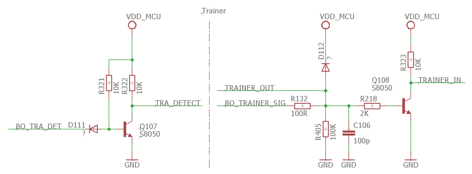
The trainer detect signal is buffered and inverted using a S8050 NPN transistor and then fed into main µC. The trainer output is passed directly, via just a 100R (R132) current limiting resistor, the input is fed again via buffering and inverting S8050 NPN transistor.
-
Martin
- Posts: 748
- Joined: 16 Feb 2018, 14:11
- Location: Warwickshire
Re: 7ch Propo + S/C mix encoder update/rewrite
Beware the first generation of RadioMaster TX16S used what looks like a normal 3.5 mm audio jack, but it's a bit different. Spektrum, JR, used to specify a mono 2-pole 3.5 mm, with the tip carrying the signal and the sleeve was ground. The more common (these days) stereo jack plugs, with an intermediate ring, often worked fine (just don't connect to the middle ring). But for some weird reason, RadioMaster used a 4-pole connector in the TX16S and the same leads that work with Spektrum and JR transmitters often don't work, or work only intermittently. There was no good reason for RadioMaster to do this: it's not like they'd wired some other signals to the 3rd and 4th poles, so you could plug in some other accessory - GPS, Bluetooth, or whatever.
This is, supposedly, the right connector to use for the RadioMaster, though not being able to spell 'length' on the diagram doesn't inspire confidence.
click for image
I read somewhere that new RadioMaster TX16S transmitters are now being supplied with the correct, Spektrum compatible, connectors - which means that the RadioMasters are no longer guaranteed to be compatible with each other! You might need a special lead with different connectors at the two ends, and it would only work when plugged in the right way round!