Simple 8-LED battery checker using Arduino clone board

Any old or new electronic projects on the go
Martin
Posts: 745
Joined: 16 Feb 2018, 14:11
Location: Warwickshire

Simple 8-LED battery checker using Arduino clone board

Post by Martin »

A friend has recently taken up slope soaring, and having previously only flown electric models, he didn't possess a suitable battery checker for testing normal receiver packs. Most of the shops seemed to be out of stock of such items, so I told him I'd make him one.

Click photos or diagrams, to get a larger view.
caseWithLead.jpg
case.jpg
I ended up making three to give away to flying friends, and I thought I'd document the process, in case anyone here fancies making one.
threeBatteries.jpg
The parts probably cost less than a similar item bought from the shops, but when you factor in your time, it's only worth making them if you enjoy the process. A benefit is that it's easy to convert this one to work for different battery types - single cell or two cell Lithium, five or six cell Nickel; but in this thread I shall concentrate on the normal 4-cell Nickel battery checker.

So I remembered I'd bought a few of the really cheap Arduino clone LGT8F boards with processors made by Logic Green, and they seemed a suitable size for this project.
LogicGreenBoard.jpg
It has the advantages over a normal Arduino (besides cheap!) of working down to 2.5V, having a 12 bit analogue input range for better resolution, and a greater choice of on-board analogue voltage references, including 2.048V and 1.024V, so it can be powered by any battery you're likely to want to test (up to 12V) and can measure low voltages more accurately than a Nano or similar. It also runs at more than double the speed of a regular Arduino, not that we need that for this project.

You can still get these on AliExpress and Ebay. Here they are on AliExpress for £3.61 each, including tax and shipping.

Avoiding the on-board LED pin (13) and the serial port pins (RXD 5~ and TXD 6~ on this board), keeping at least one analogue input free for measuring the battery voltage, and choosing the other pins in a sensible order for connecting to the LEDs easily, I created this schematic.
schematic.png
That's enough for this first post. In my next posts, I'll detail the build process and attach the STL files and Arduino sketch.
Last edited by Martin on 17 Aug 2022, 10:44, edited 7 times in total.
User avatar
Wayne_H
Posts: 811
Joined: 17 Feb 2018, 05:26
Location: Temora, NSW. Australia
Contact:

Re: Simple 8-LED battery checker using Arduino clone board

Post by Wayne_H »

Another handy gadget thanks Martin. Added to my list of things to build 😀
Cheers,

Wayne
Once a Retrobate, always a Retrobate............ ;)
Martin
Posts: 745
Joined: 16 Feb 2018, 14:11
Location: Warwickshire

Re: Simple 8-LED battery checker using Arduino clone board

Post by Martin »

Attached is the Arduino Sketch, and the STL files for the case.
Attachments
caseSTLfiles.zip
STL files for 3D-printing the case
(85.02 KiB) Downloaded 100 times
nickelFourCellTester.zip
Arduino sketch
(1.63 KiB) Downloaded 95 times
Martin
Posts: 745
Joined: 16 Feb 2018, 14:11
Location: Warwickshire

Re: Simple 8-LED battery checker using Arduino clone board

Post by Martin »

Parts required:
  • 3D-printed case top and bottom
  • 'Arduino' clone board: Mine has printed on the bottom "LGT8F328P SSOP20 MiniEVB" and "BTE17-13" I guess that last one could just be a batch number. There is a manufacturer name/logo which looks like BAITE in a rather stylized font, with the 'A' looking more like a mountain or teepee, plus a couple of chinese characters
  • Four green 3mm LEDs
  • Three yellow 3mm LEDs
  • One red 3mm LED
  • Five 220-ohm 1/4-watt resistors. Four of them are connected in parallel to provide a roughly 100mA current draw when testing a battery. You could use a single 47-ohm or 56-ohm resistor in place of those four, but it would need to have at least a half-watt rating, or one-watt to be safe.
  • One 1k2 resistor
  • One 2k2 resistor
  • Scrap of veroboard (stripboard) for mounting the resistors (optional)
  • 'Servo-lead' with appropriate (probably male pins, female shroud) connector for plugging to your battery / harness when testing. I cut up some old servo 'Y-leads' to obtain mine
  • Bit of heat-shrink tubing, or insulating tape
  • Small cable tie to act as 'anti yank-out' cable retainer
  • Bits of tinned copper wire
You'll also need another Arduino to act as a programming device when flashing the program or bootloader to the board (you CAN'T use a USBasp on these boards). If you flash a bootloader to the board (or if your board comes with a bootloader preloaded), you can then program it with a normal USB to serial adapter. For this project, you don't really need to flash the bootloader, as you only have to upload the sketch once. The sketch optionally prints out data from its serial pins - you shouldn't need to see that data as it was just for my initial debugging - but if you want to see it you'll need a USB to serial adapter for that.
serialInterface.jpg
This type of serial adapter has its pins in the right order for directly connecting to the board (once you bend the 3.3V pin out of the way).
serialInterfaceConnected.jpg
The row of holes at the opposite end of the board to where the serial interface is plugged in, is where you connect your other Arduino, to flash the program or bootloader. The LGT8F328P chip is programmed / flashed via a so-called SWC/SWD interface.
Last edited by Martin on 16 Aug 2022, 17:00, edited 1 time in total.
Martin
Posts: 745
Joined: 16 Feb 2018, 14:11
Location: Warwickshire

Re: Simple 8-LED battery checker using Arduino clone board

Post by Martin »

Building. Click photos for a larger view.

Start by shoving the LEDs into the 'top' of the 3D-printed box. The LEDs should be rotated so that all their pins form a straight line, with the longer (positive anode) end of the LEDs all towards the same end, which I'll call the 'top'.
one.jpg
Bend all the longer legs over to the left.
two.jpg
Put a bit of tinned copper wire to connect all the bent-over LED legs together. It's easiest to weave the wire over one leg and under the next - up and down like basket weaving. Once the wire is positioned, solder it to each leg with a blob of solder.
three.jpg
Solder one of the 220-ohm resistors to the commoned-together LED legs, and bend it to roughly the position shown. Bend the remaining legs of the LEDs, bottom two over to the left, and top six to the right, roughly as shown. The idea is to get the sticking up resistor leg in the right place to plug into one of the board's VCC pins, and the LED legs in the right places to plug into the connections shown on the schematic. Test fit the board a few times and gradually adjust the positions of the bends in the wires till it fits easily. Don't solder it to the wires, yet.
four.jpg
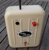
Notice I've turned the case top, with its LEDs upside-down for this photo, compared to the previous ones. I didn't do that just to confuse you - it was to get the writing on the back of the board the right way up! :D
resistorVeroboard.jpg
The remaining resistors are best soldered to a bit of veroboard (stripboard) as shown. I did it with the copper side of the veroboard facing up. You could do it the other way round, in which case you'd solder the wires that connect the veroboard to the Arduino board to the veroboard first (the opposite of the process I detail below). The two outer tracks of the veroboard are GND and Battery +ve. The next two tracks inwards are commoned together and to the A5 analogue input pin to the Arduino board: the two resistors, 1k2 and 2k2 connect to those tracks: these form the potential divider for scaling the battery input voltage down to less than 2V, to suit the A/D range. The centre track of the veroboard is unused. There's no drilling of the veroboard - just five straight tracks (four used) and one link wire, as shown.
veroMountWires.jpg
Solder three bits of wire to the Arduino board to attach the veroboard to. These go to the pins labelled GND, RAW, and A5 SCL.
veroMounted.jpg
Solder the veroboard to the mounting wires. Make sure it's not shorted to the back of the board - cut the resistor wires off short, and leave a gap of about 1mm between the resistor wires and the back of the PCB.
topReadyForBatteryWire.jpg
There are two LEDs (power and 'blinky') built onto the top of the Arduino PCB. These are a nuisance because they shine through the translucent 3D-printed case, distracting attention from the main voltage-indicating (3mm) LEDs. Stick a bit of light obscuring tape over these LEDs, or remove them from the board altogether. Do it at this stage before soldering the boards to the main 3mm LED legs, because it's tricky once the LEDs are in the way.

Now solder the assembled board/veroboard to the LEDs in the case top. Try to align it so that it's central to the case top - or it won't fit into the bottom of the case!
edgeView.jpg
Look at the assembly edge-on, before and after soldering, to make sure that things are aligned without shorting.
midAir.jpg
You can manage without the veroboard - but it's tricky to solder all the resistors together in mid-air, without accidentally shorting to the back of the board.

If you're using a 'servo' lead with three wires, cut back the signal wire, and put a bit of heat-shrink tubing over the wire, or wrap it in insulating tape. If someone manages to plug their battery into the tester with polarity reversed (possible with 'JR' vs 'Futaba' connectors) then it won't matter - the positive lead is always the centre one, and if they've connected the battery GND to the signal wire, it won't matter providing that it's insulated.
leadSoldered.jpg
Thread the servo lead through the bottom part of the case, the correct way round so that when assembled there are no twists. Solder it to the veroboard with the black (dark) wire connecting to the veroboard track linked to Arduino GND, and the battery positive wire to the veroboard track linked to Arduino RAW. Use a small cable tie as a stopper to prevent clumsy users pulling the wires off their soldered connections.

Don't clip the top and bottom of the box together yet. You should test the board and calibrate the low and high voltage points before doing that. I'll cover that in my next posts.
bluejets
Posts: 317
Joined: 19 Jun 2019, 04:09

Re: Simple 8-LED battery checker using Arduino clone board

Post by bluejets »

Hi Martin,
I think these are the same from Aliexpress......maybe not..??

https://www.aliexpress.com/item/1005004 ... 68.html
Attachments
LGT8F328P.jpg
Martin
Posts: 745
Joined: 16 Feb 2018, 14:11
Location: Warwickshire

Re: Simple 8-LED battery checker using Arduino clone board

Post by Martin »

Those are a bit different, and in many ways better: they use the LQFP32 (32-pin 4-sided) version of the chip instead of the SSOP20 (20-pin 2-sided) version. The SSOP20 chip doesn't have enough pins to bring out all of the signals from the silicon inside - which is why the board I used has some signals (e.g. A2) missing, and many signals (e.g. 4 3~) shared on the same physical pin.

The 32-pin ones cost hardly any more than the 20-pin ones, so would be worth buying if you have a project that needs more pins.
My sketch works on those 32-pin versions - probably worth altering the chosen pins to drive the LEDs to make them line up better with the board pin-out (a simple change to one line of the sketch, and a modified version of the schematic). The PCB is also slightly longer by 2.54 mm so would need a slightly modified version of the case to fit it.

If anyone wants to try the 32-pin version, let us know in this thread, and I'll upload the alternative versions of the sketch / schematic / STL files.

If you're not so bothered about the size of the board, there are also the NANO-sized ones, which have a USB connector and serial converter on board. Here they are on AliExpress for less than £4, including tax and shipping. https://www.aliexpress.com/item/1005001693711452.html I think they're a bit too bulky for a battery checker though.
Last edited by Martin on 17 Aug 2022, 10:53, edited 2 times in total.
Martin
Posts: 745
Joined: 16 Feb 2018, 14:11
Location: Warwickshire

Re: Simple 8-LED battery checker using Arduino clone board

Post by Martin »

These are the ones I used - on AliExpress now for £3.61 each, including tax and shipping - and cheaper if you buy several: https://www.aliexpress.com/item/33013927629.html Mine are the ones with the 5V regulator, but the 3.3V regulator version would be fine too. The chip works down to 2.5V or less, so even when you're powering the board via a 'flat' battery that's being checked, and via the RAW pin and losing a little voltage through the regulator, the chip still works, and the analogue input readings are still accurate (the chip uses its internal 2.048V reference for this project, so even a 'flat' battery of say 3.5V, will still power the chip and light up the lowest voltage, red, LED).
Martin
Posts: 745
Joined: 16 Feb 2018, 14:11
Location: Warwickshire

Re: Simple 8-LED battery checker using Arduino clone board

Post by Martin »

Here's how you calibrate it. Ideally you use a variable power supply, and voltmeter. The sketch is roughly calibrated by default when you upload it to a new board - but obviously the exact calibration depends on the accuracy of your two potential-dividing resistors (1k2 and 2k2). If you don't have a voltmeter, just use the gadget without calibration - it will be pretty close to correct, and you can cross-check it against any other battery checkers your fellow flyers may have at the flying site.

If you don't have a variable power supply, but do have a voltmeter, you could just hook up a freshly charged battery, make the 'high voltage calibration' link a short while after connecting the battery (ideally wait till the straight-from-charge voltage has subsided to 5.36V). Then connect a run down battery (or wait patiently while it runs down) and make the 'low voltage calibration' link when the voltage falls to 4.80V.

User avatar
tiptipflyer
Posts: 393
Joined: 16 Feb 2018, 22:49
Location: Germany

Re: Simple 8-LED battery checker using Arduino clone board

Post by tiptipflyer »

Thank you Martin for another great project.
I enjoy building even more than using, so I have to build one.
The LGT8F´s are on the way from China, and the case is on order from a friend.
Thanks for posting again.

Frank
Post Reply