...a case for the Mode Zero stick!

Single to Multi propo
Post Reply
Tobe
Posts: 711
Joined: 16 Feb 2018, 06:19
Location: Varberg or Stockholm, Sweden

...a case for the Mode Zero stick!

Post by Tobe »

This is a project for those of you that once made the DIY stick 3D-printed that I presented a while ago.
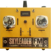
We are talking about a 3D printed Tx-case for 4+2 channels and a few toggle switches.
The size of the Tx is quite compact bur there shouldn't be any issues with space however you might have to opt for solder directly to the board your wires instead of using pin headers.
...the result av the project!
Mode Zero Tx.png
Mode Zero .pdf
(23.4 KiB) Downloaded 92 times
20241216_190448.jpg
The printed parts for the case with the standard Mode_Zero stick
3D-printed in ABS but PLA will do, 0,4 mm nozzle,50 % infill with supports, my printer needed a total of 14 hrs between case and sticks.
Here are both the .stp-files as the .stl.
Unfortunately I don't have much spare time available for a full instruction but if you manage the DIY-sick this should not that difficult but if you are in doubt ask and I will do my best to assist you.
The .step file should allow you to make modifications like adding or removing features.
DIY-More Pro Mini size Encoders will fit nicely
viewtopic.php?f=42&t=1501
Knob.STL
(110.53 KiB) Downloaded 91 times
Knob-Short.STL
(111.31 KiB) Downloaded 55 times
Mode Zero stl (2).zip
(267.83 KiB) Downloaded 99 times
Mode Zaro step (2).zip
(655.96 KiB) Downloaded 92 times
Mode Zero stl (3).zip
(268.02 KiB) Downloaded 97 times
Mode Zaro step (3).zip
(515.25 KiB) Downloaded 71 times

Progress:
I have updated with a new version, changes are the toggle switch holes which have been enlarged and some plastic has been added, nothing that affect the function but makes little more stronger.
During the X-mas holiday and as my mane printer is free from making its bred and butter I will do this project step by step publishing relevant instructions and pictures as the building process goes along.
Please let me know if there any details that you might want to be added and/or removed and if reasonable I will try to offer the update file
Cleaning up the printed part for the sticks
20241225_105429.jpg
20241225_102300.jpg
First position your switches and connect them, it's quite tight so you have to be carefull and thest with the sticks in position
Showing here a "standard" DIY More board
...not connected yet but the wires are there...have to decide for a version

2024-12-24
Have noticed an error in the file for the hatch so here is a revise file. I will start in a few days a building instructions as I build one from scratch in accordance with the files published here.
Updated hatch.zip
(18.52 KiB) Downloaded 41 times
Front....
Front....
Back, notice ths 2 hatches
Top one could a Lemon RF-module but here I show my own nRF24 based one and the bottom one a 800 mAh 2s lipo and...
...access to the dip switches and the ICSP
...a Strong board wired up with Mike_K F3A sketch but could be reprogrammed easely w/o removing the back cover.
Cheers,

Tobe
User avatar
Mike_K
Posts: 762
Joined: 16 Feb 2018, 06:35
Location: Hertfordshire

Re: ...a case for the Mode Zero stick!

Post by Mike_K »

Another great project, who said DIY R/C sets were a thing of the past?
User avatar
Wayne_H
Posts: 830
Joined: 17 Feb 2018, 05:26
Location: Temora, NSW. Australia
Contact:

Re: ...a case for the Mode Zero stick!

Post by Wayne_H »

Fabulous Tobe. Great work again.

Thanks for sharing mate ;)
Cheers,

Wayne
Once a Retrobate, always a Retrobate............ ;)
User avatar
Shaun
Posts: 1229
Joined: 15 Feb 2018, 21:49
Location: West Yorkshire

Re: ...a case for the Mode Zero stick!

Post by Shaun »

Excellent job Tobe.
User avatar
stuart mackay
Posts: 587
Joined: 01 Mar 2018, 10:38
Location: Swaffham, Norfolk
Contact:

Re: ...a case for the Mode Zero stick!

Post by stuart mackay »

Another Plus One for what everyone has already said above! :lol:
waynew17
Posts: 29
Joined: 14 Feb 2022, 17:24

Re: ...a case for the Mode Zero stick!

Post by waynew17 »

Very impressive case Tobe. Thanks for sharing the stl files. I will definitely print one when I get back home in the spring. I printed your joysticks last year. It was a fun project, and they have worked out great.

I noticed the boards that you installed on the back of the slider trim pots. I'm assuming these are for adjusting the amount of trim. Great idea. It looks like the pot is in series with the wiper on the slider pot. What value pot do you use on the boards? Thanks.
Tobe
Posts: 711
Joined: 16 Feb 2018, 06:19
Location: Varberg or Stockholm, Sweden

Re: ...a case for the Mode Zero stick!

Post by Tobe »

Hi Wayne, good to hear from you and would imagine that you are still in Florida.
From memory I would guess 20k and you would probably end having the trim pot set to 3/4, an easy way to set the gain for the trims instead to try and error loose resistors. The point is that in my stick I use the full movement of the trim pot.
Cheers,

Tobe
Post Reply